Electric connector

An electrical connector and electrical technology, which is applied in the direction of connection, circuit, and parts of the connection device, can solve the problem that the double conductive path of the conductive terminal cannot be guaranteed to work stably, the contact is unstable, and the electrical connector and the chip module are affected. To reduce self-inductance, improve high-frequency performance, and ensure normal operation

Active Publication Date: 2018-11-23
DEYI PRECISION ELECTRONIC IND CO LTD PANYU
View PDF4 Cites 3 Cited by
  • Summary
  • Abstract
  • Description
  • Claims
  • Application Information

AI Technical Summary

Problems solved by technology

[0003] However, when this conductive terminal structure is accommodated in the receiving groove, since the pressing arm is horizontally arranged, when the third elastic arm abuts against the pressing arm, the pressing arm and the third pressing arm The positive force between the elastic arms is insufficient, that is, the contact between the pressing arm and the third elastic arm is unstable, so when the chip module is mounted on the electrical connector, the conductive terminal cannot be guaranteed. The stable operation of the double conductive path, thus affecting the stable electrical connection between the electrical connector and the chip module

Method used


Image

  • Electric connector
  • Electric connector
  • Electric connector

Examples


Embodiment Construction

[0030] In order to facilitate a better understanding of the purpose, structure, features, and effects of the present invention, the present invention will now be further described in conjunction with the accompanying drawings and specific embodiments.

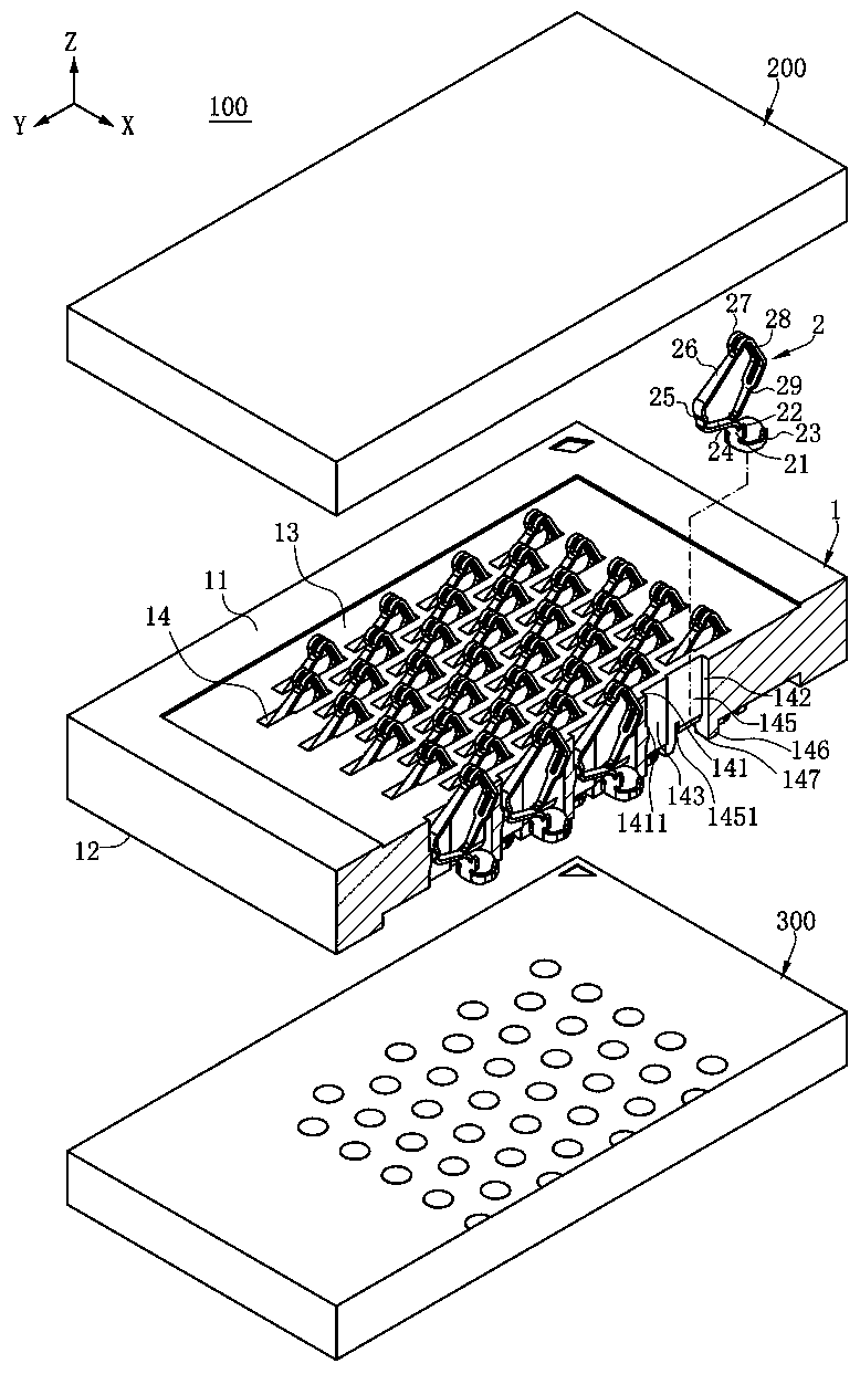
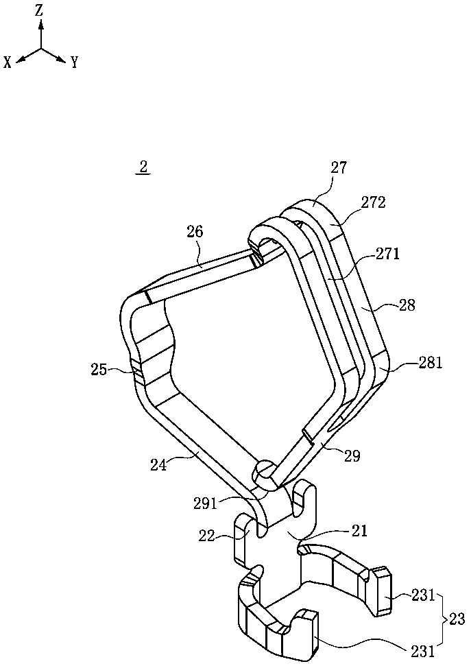
[0031] Such as Figure 1 to Figure 7 As shown, it is the first embodiment of the electrical connector of the present invention. The electrical connector 100 of the present invention is used to electrically connect a chip module 200 to a circuit board 300. The electrical connector 100 includes an insulating body 1 and a device Multiple terminals 2 on the insulating housing 1 .

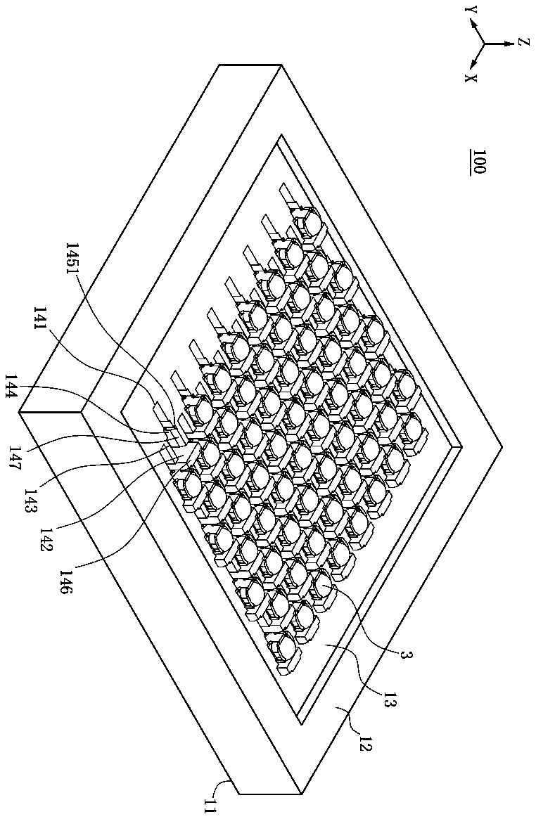
[0032] Such as figure 1 , image 3 and Figure 4 As shown, the X-axis is defined as the front-to-back direction, the Y-axis is the left-right direction, and the Z-axis is the up-down direction. The insulator body 1 is provided with an upper surface 11 and a lower surface 12, and is recessed from the upper surface 11 to form a storage Area 13, the rec...


PUM


Abstract

The invention discloses an electric connector which is used for electrically connecting a chip module to a circuit board. The electric connector is characterized by comprising an insulating body and at least one terminal; the insulating body is arranged on the circuit board and provided with at least one containing groove; the at least one terminal is arranged in the containing grooves and electrically connected with the circuit board; and in each terminal, a base is arranged and fixed to the containing groove, an abutting pressing arm is formed by extending upwards from the base to one side of the corresponding containing groove, a first elastic arm is formed by extending upwards from the base to the other end of the containing groove, a second elastic arm is connected with the first elastic arm and extends downwards, the first elastic arm is exposed to the insulating body and used for being connected with the chip module, a third elastic arm is formed by extending to the abutting pressing arm, and when the chip module presses the terminal, the third elastic arm moves and abuts against the abutting pressing arm. According to the electric connector, by obliquely arranging the abutting pressing arms, the positive force between the third elastic arms and the abutting pressing arms is greater, therefore, abutting between the third elastic arms and the abutting pressing arms is more reliable, and then stable contact between the terminals and the chip module is guaranteed.

Description

technical field [0001] The invention relates to an electrical connector, in particular to an electrical connector with a more stable electrical connection between a terminal and a chip module. Background technique [0002] An electrical connector commonly used in the industry is used to electrically connect a chip module to a circuit board. The electrical connector has an insulating body and a plurality of conductive terminals. The insulating body is provided with a plurality of receiving grooves corresponding to accommodate a plurality of conductive terminals. terminals. The basic structure of the conductive terminal is as follows: the conductive terminal has a base, which is bent horizontally and extends rightward from the bottom of the base to form a pressing arm, and is bent and extended downward from the end of the pressing arm to form a welding part. A first elastic arm is bent and extended from the upper right direction of the base, and a contact portion is formed at...

Claims


Application Information

Patent Timeline
Patent Type & Authority Applications(China)
IPC IPC(8): H01R13/187H01R13/24H01R12/71
CPCH01R12/716H01R13/187H01R13/2407
Inventor 黄常伟
Owner DEYI PRECISION ELECTRONIC IND CO LTD PANYU
Why Eureka
Try Eureka