A capacitive connection structure to reduce inductance

A connection structure and capacitance technology, which is applied to multiple fixed capacitors and parts of fixed capacitors, can solve problems such as capacitor damage, large unbalance, and circuit unbalance, and achieve current stability, self-inductance reduction, and circuit balance. Effect

Active Publication Date: 2018-07-31
NINGBO JIANGBEI GOFRONT HERONG ELECTRIC
View PDF7 Cites 0 Cited by
  • Summary
  • Abstract
  • Description
  • Claims
  • Application Information

AI Technical Summary

Problems solved by technology

Because of the inductance and resistance of the busbar itself, its equivalent circuit is as follows figure 2 As shown in the figure, it can be seen that the equivalent circuit of this capacitor connection structure has multiple small inductors forming a network connection. Under high-frequency AC applications, the entire circuit will be unbalanced due to the imbalance of inductance. The current is not equal, the higher the frequency, the greater the unbalance, which will cause harm to the capacitor

Method used


Image

  • A capacitive connection structure to reduce inductance
  • A capacitive connection structure to reduce inductance
  • A capacitive connection structure to reduce inductance

Examples


Embodiment 1

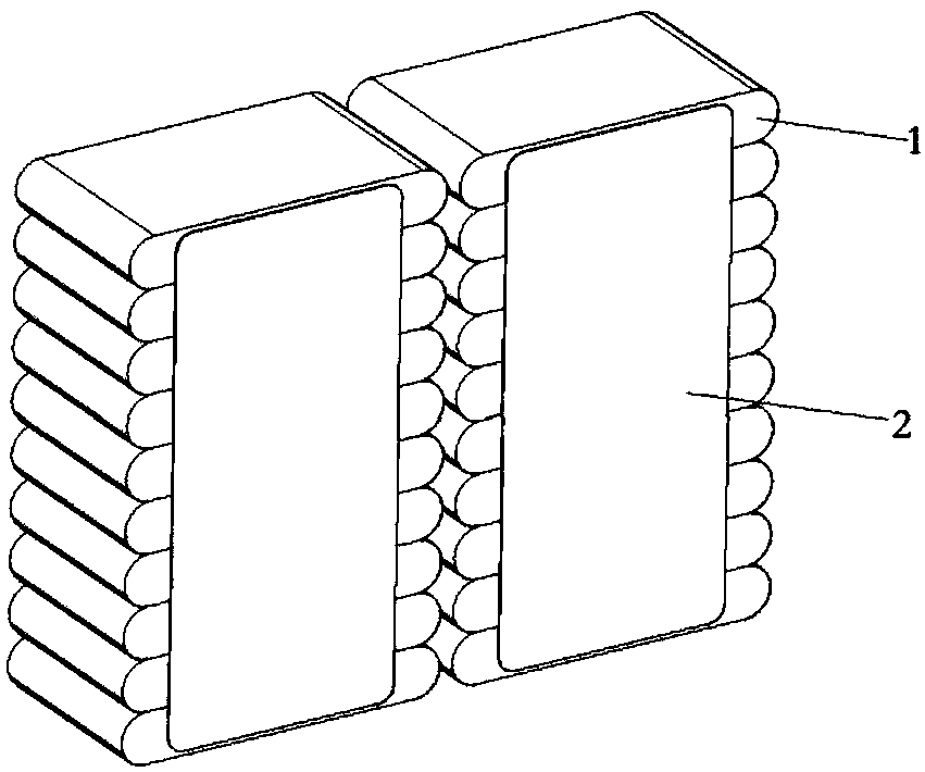
[0023] A capacitive connection structure for reducing inductance, comprising layered stacked capacitor cores and bus bars for connecting the capacitor cores.

[0024] The top and bottom of each capacitor core are respectively provided with an upper busbar and a lower busbar. The shape and structure of the upper and lower busbars are the same, and the installation direction is opposite. The lower busbar is vertically flipped over the upper busbar. One end of the busbar is the lead-out part, which is used to connect the positive and negative lead-out wires. A connecting portion is provided in the middle of the busbar for connecting the capacitor core. The connection parts of the upper and lower busbars are respectively connected with the gold-sprayed surfaces on both sides of the capacitor core of this layer, forming a layer of capacitor connection structure. According to the requirement of capacitance capacity, the internal structure of the power capacitor is formed by stacki...

Embodiment 2

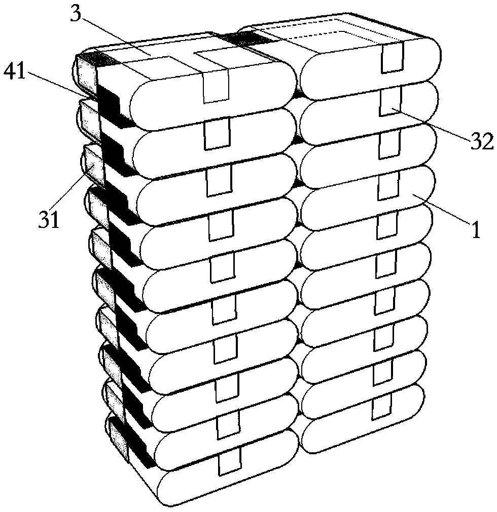
[0027] Such as image 3 and Figure 4 As shown, a capacitor connection structure for reducing inductance is formed by stacking multilayer capacitor cores 1. The capacitor connection structure has 10 layers in total, each layer has two flat capacitor cores 1, and the capacitor cores in each layer Sub-1s are connected through busbars.

[0028] Such as Figure 5 As shown, the top of each capacitor core 1 is provided with an upper busbar 3, and the bottom is provided with a lower busbar 4 vertically turned over from the upper busbar 3. One end of the busbar is provided with a lead-out bend, and the middle part is provided with two connection bends, which are respectively used to connect the two capacitor cores 1 of this layer. The bending directions of the lead-out bends and the connection bends are the same. The connection bend 32 of the upper busbar is connected to the gold-sprayed solder spot on one side of the capacitor core 1, and the connection bend 42 of the lower busbar...

Embodiment 3

[0032] The difference between this embodiment and the foregoing embodiments lies in that the shape of the capacitor core is cylindrical.


PUM


Abstract

The invention discloses a capacitance connecting structure for reducing inductance. The capacitance connecting structure comprises capacitance cores arranged in a layered stacking manner, and busbars used for connecting the capacitance cores, wherein the busbars comprise lead-out parts and connecting parts; the lead-out parts are used for connecting positive and negative lead-out conductors; the connecting parts are used for connecting the capacitance cores; an upper busbar is arranged at the top of each capacitance core; a lower busbar which has vertical flip with each upper busbar is arranged at the bottom of each capacitance core; and connecting parts of the upper busbars and the lower busbars are respectively connected with metal spraying surfaces on the two sides of the capacitance cores. The capacitance connecting structure is an internal structure of a power capacitor; a high-capacity power capacitor can be obtained by adjusting the quantity and an arrangement manner of the capacitance cores as required; self-inductance of the power capacitor can be reduced by a connecting manner of the busbars; circuit equilibrium of the capacitor at high frequency can be ensured; passing current of each capacitance core is stable; and an application characteristic of the capacitor at the high frequency can be greatly improved.

Description

technical field [0001] The invention relates to the field of power capacitors, in particular to a capacitive connection structure for reducing inductance. Background technique [0002] Power capacitors are common elements in power circuits or power systems to stabilize voltage and / or current from one device or component to another. Capacitors reduce current fluctuations during power system operation by compensating for inductive loads or absorbing voltage fluctuations or voltage peaks caused by the device. When the rated power of the power system is high, multiple capacitor cores need to be connected to increase the overall capacitance of the power capacitor. [0003] At present, capacitor cores used in capacitors on the market adopt non-inductive winding, and the self-inductance of each core is extremely small, so the self-inductance of capacitors is mainly determined by the self-inductance of the connecting busbar. The capacitor core connection structure in the prior art...

Claims


Application Information

Patent Timeline
Patent Type & Authority Patents(China)
IPC IPC(8): H01G4/002H01G4/38
CPCH01G4/002H01G4/38
Inventor 赵亮潘振李林
Owner NINGBO JIANGBEI GOFRONT HERONG ELECTRIC
Why Eureka
Try Eureka