Granular terminal automatic feeding and crimping device

A technology for automatic feeding and crimping equipment, applied in connection, electrical components, circuits, etc., can solve problems such as low work efficiency, complex equipment structure, unfavorable terminal positioning, etc., to improve efficiency, improve extrusion efficiency, and improve labor efficiency effect

Pending Publication Date: 2018-11-23
张晓波
View PDF1 Cites 12 Cited by
  • Summary
  • Abstract
  • Description
  • Claims
  • Application Information

AI Technical Summary

Problems solved by technology

[0002] In the prior art, in the manufacturing process of electronic products, various cables such as wire bundles need to be crimped through the terminals, and for the bulk terminals, the existing bulk terminals are mainly manually grasped by the terminals for crimping. , this method is not conducive to the positioning of the terminal on the one hand, and on the other hand, the work efficiency is low; the Chinese patent authorization announcement number CN203367724U has announced a kind of bulk terminal crimping device, which is used to crimp the bulk terminal with the electric wire in turn, and the device It includes a vibrating plate, a direct vibrating feeder, a positioning component and a crimping component. Both ends of the direct vibrating feeder are connected to the vibrating plate and the positioning component respectively. A plurality of the granular terminals are sorted and output to the The direct vibration feeder is sequentially delivered to the positioning assembly through the direct vibration feeder, and the positioning assembly positions the bulk terminal to the crimping position with the electric wire, and passes through the crimping assembly Crimp the bulk terminal with the wire
Although the above-mentioned equipment can realize automatic feeding and crimping of bulk terminals, the structure of the equipment is complex and difficult to operate

Method used


Image

  • Granular terminal automatic feeding and crimping device
  • Granular terminal automatic feeding and crimping device
  • Granular terminal automatic feeding and crimping device

Examples


Embodiment 1

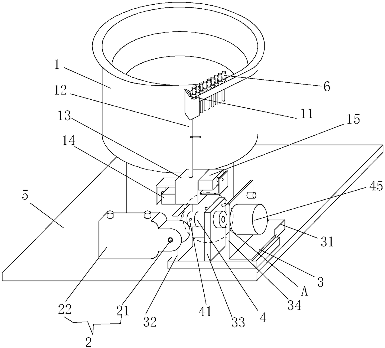
[0037] Such as figure 1 As shown, the automatic feeding and crimping equipment for bulk terminals in this embodiment includes a base 5 and a vibrating plate 1 placed on the base 5, the terminals to be crimped are placed in the vibrating plate 1, and the discharge port of the vibrating plate 1 Below 11, a terminal drop tube 12 is vertically arranged, and the inner diameter of the terminal drop tube 12 matches the maximum diameter of the terminal to be crimped with a small gap, so that the terminals in the vibrating plate 1 can be sorted and output by the vibrating plate 1, and then they can enter the terminals vertically in sequence. The drop tube 12, and due to the limitation of the inner diameter of the terminal drop tube 12, the terminals entering the terminal drop tube 12 are arranged end-to-end in sequence. Nylon straps are embedded in the inner wall of the vibrating plate 1 to prevent the terminals from directly contacting the metal inner wall of the vibrating plate 1 dur...

Embodiment 2

[0049] On the basis of Embodiment 1, the automatic feeding and crimping equipment for bulk terminals in this embodiment has the following deformations: the automatic feeding and crimping equipment for bulk terminals in this embodiment is suitable for performing crimping on terminals with crimping parts placed at the front Feed crimping, such as Image 6 As shown, the terminal ferrule of this embodiment also includes a threaded portion 463, a slot 464, a through hole 462 and a tapered hole 461. By adjusting the axial lengths of the tapered hole 461 and the through hole 462, the tapered hole 461 An accommodating cavity 465 suitable for arranging the terminal tail end and the reducing section is formed in the terminal ferrule 46 .

[0050] When the three-stage terminal positioning rotating shaft 4 is in the initial state, the opening of the terminal ferrule 46 is placed directly below the opening at the bottom end of the terminal accommodating groove, and the terminal ferrule 46 ...

Embodiment 3

[0053] The bulk terminal automatic feeding and crimping equipment described in Example 1 is suitable for terminals with crimping parts placed at the tail end, such as aviation pins 6, such as Figure 7As shown, the aviation pin 6 includes a pin reducing section 63 in the middle, the front part of the pin reducing section 63 is the front end 62 of the pin, and the rear part of the pin reducing section 63 is the tail end crimping part 61.

[0054] The automatic feeding and crimping method for aviation pins includes the following steps:

[0055] A. Close the lower stopper cylinder 14 of the terminal accommodating groove, open the upper stopper cylinder 15, start the vibrating plate 1, and arrange the aviation pins 6 in the vibrating plate 1 in an orderly manner, so that the tail ends of the aviation pins 6 The crimping part 61 is on the top, the front end 62 of the pin is on the bottom and reaches the discharge port one by one, and enters the terminal drop tube 12 and the termin...


PUM


Abstract

The invention relates to a granular terminal automatic feeding and crimping device and a working method thereof. The granular terminal automatic feeding and crimping device comprises a vibration disc,a terminal falling pipe, a terminal positioning rotating shaft, a movable sliding table and a crimping assembly; the terminal falling pipe is vertically arranged below a discharge hole of the vibration disc, so that a terminal to be crimped in the vibration disc can vertically enter the terminal falling pipe; the terminal positioning rotating shaft is rotatably arranged on the movable sliding table; a terminal inserting hole is formed in the terminal positioning rotating shaft in the radial direction of the terminal positioning rotating shaft, and the terminal inserting hole is formed below the outlet of the terminal falling pipe in the initial state, so that the to-be-crimped terminal in the terminal falling pipe can enter the terminal inserting hole in falling off, and the crimping partof the terminal is arranged outside the terminal inserting hole; the crimping assembly comprises a crimping jaw; and the crimping jaw is arranged on one side of the terminal positioning rotating shaft, so that after the terminal to be crimped enters the terminal inserting hole and after the terminal positioning rotating shaft rotates, the crimping part of the terminal arranged outside the terminal inserting hole can enter the crimping jaw by moving the movable sliding table.

Description

technical field [0001] The invention relates to the technical field of bulk terminal processing, in particular to automatic feeding and crimping equipment for bulk terminals. Background technique [0002] In the prior art, in the manufacturing process of electronic products, various cables such as wire bundles need to be crimped through the terminals, and for the bulk terminals, the existing bulk terminals are mainly manually grasped by the terminals for crimping. , this method is not conducive to the positioning of the terminal on the one hand, and on the other hand, the work efficiency is low; the Chinese patent authorization announcement number CN203367724U has announced a kind of bulk terminal crimping device, which is used to crimp the bulk terminal with the electric wire in turn, and the device It includes a vibrating plate, a direct vibrating feeder, a positioning component and a crimping component. Both ends of the direct vibrating feeder are connected to the vibrati...

Claims


Application Information

Patent Timeline
Patent Type & Authority Applications(China)
IPC IPC(8): H01R43/055
CPCH01R43/055
Inventor 张晓波
Owner 张晓波
Why Eureka
Try Eureka