Cable leading-down facility for established double-circuit strain tower

A technology for tension towers and cables, applied in the spatial arrangement/configuration of cables, etc., can solve problems such as not too close spacing, waste of resources, poor overall aesthetics, etc., achieve a wide range of applicable voltage levels, reduce construction costs, and avoid demolition and reconstruction Effect

Pending Publication Date: 2018-11-23
ANHUI HUADIAN ENG CONSULTATING & DESIGN +4
View PDF0 Cites 0 Cited by
  • Summary
  • Abstract
  • Description
  • Claims
  • Application Information

AI Technical Summary

Problems solved by technology

[0002] In the actual project of cable lead-down of overhead transmission lines, due to the influence of line path, surrounding environment and other factors, the cable lead-down point may appear in the center of the line, near the built tower, etc., especially near the built tension tower. The new tension-type cable terminal tower and the built-up tension tower form a small isolated gap, which increases the unbalanced tension on both sides of the built-up tension tower, which is difficult to meet the use conditions and needs to be dismantled and rebuilt; the new linear cable terminal and the built-up The tower is affected by the mutual influence of the pole tower foundation, the distance between the two towers should not be too close, and the utilization rate of the newly built straight tower is not high, the waste of resources is serious, and the overall aesthetics is poor

Method used


Image

  • Cable leading-down facility for established double-circuit strain tower
  • Cable leading-down facility for established double-circuit strain tower
  • Cable leading-down facility for established double-circuit strain tower

Examples


Embodiment Construction

[0013] In order to make the technical means, creative features, goals and effects achieved by the present invention easy to understand, the present invention will be further described below in conjunction with specific embodiments.

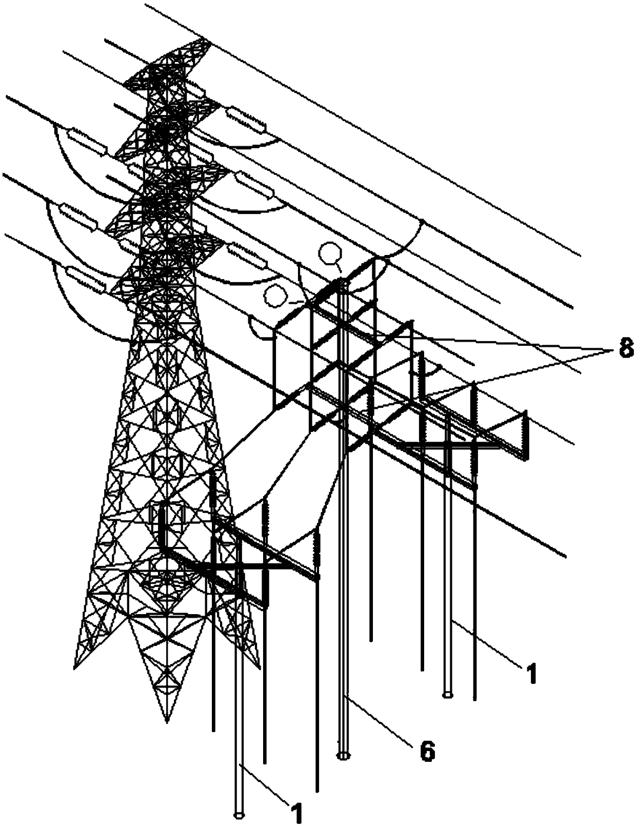
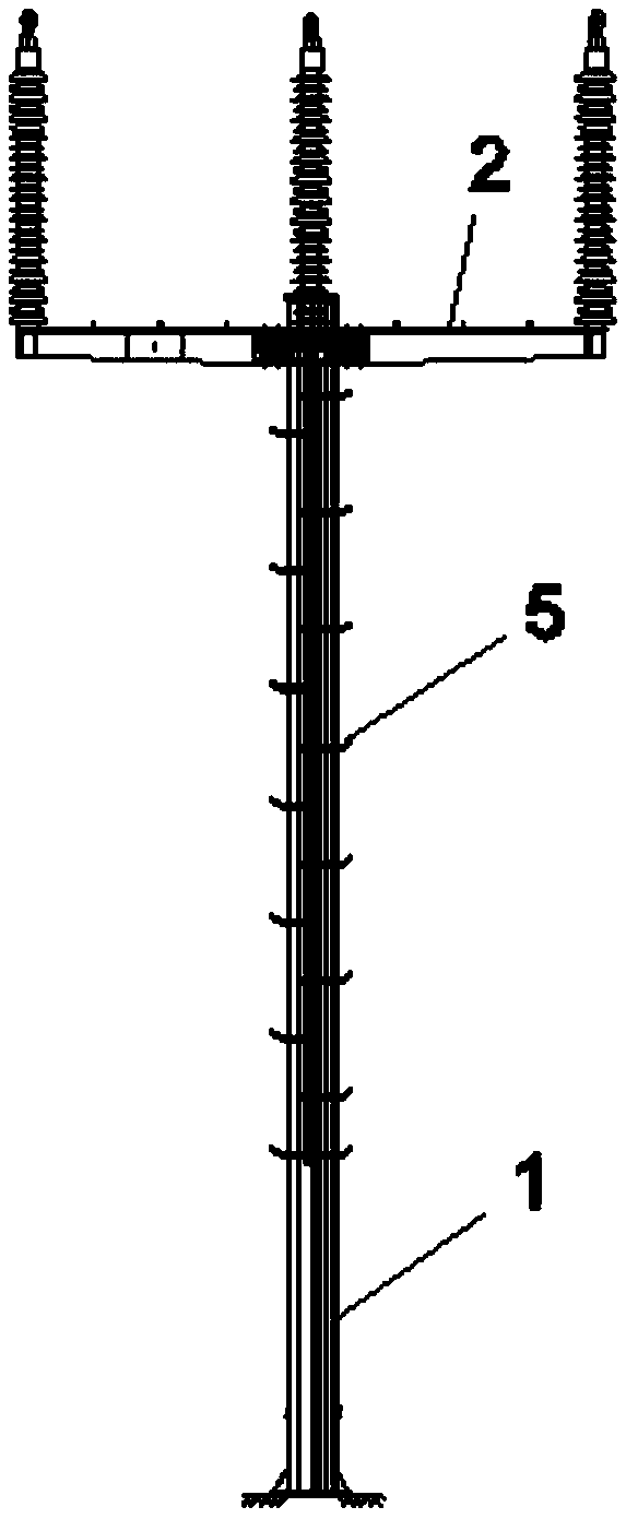
[0014] Such as Figure 1-4 As shown in Fig. 1, a cable down-conduction facility for an established double-circuit tension tower consists of two parts: an independent cap and a down-conductor tower.

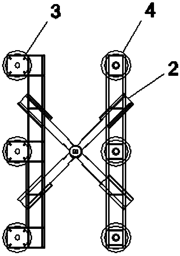
[0015] The independent platform includes a support rod 1 , a support platform 2 , a seat type cable terminal 3 , and a seat type lightning arrester 4 .

[0016] The support platform 2 is set above the cross arm at the top of the support rod 2, and is composed of an "X"-shaped cross arm and a "one"-shaped cross arm. The angle between the "X"-shaped cross arm and the transmission line is 45 degrees, and the upper part is used for supporting "One"-shaped cross arm, seat type cable terminal 3, seat type lightning arrester 4, the center is located on the ...


PUM


Abstract

Disclosed is cable leading-down facility for an established double-circuit strain tower. The cable leading-down facility consists of an independent bearing platform and a leading-down rod tower, wherein the independent bearing platform comprises a support platform; the support platform is arranged above cross arms at the top end of a support rod, and is composed of an X-shaped cross arm and a horizontal-line-shaped cross arm, wherein the leading-down rod tower comprises a rod body, a supporting column insulator and auxiliary cross arms, wherein the rod body is close to the established strain tower; and the auxiliary cross arms are parallel to the line direction, and a plurality of layers of the auxiliary cross arms are arranged at equal intervals between the top end of the rod body and theindependent bearing platform. The device is suitable for being tightly attached to the strain tower for construction without changing the stress of the strain tower on the lower side, so that dismantling and rebuilding of an old tower is prevented; and compared with a newly-built linear and strain tower, the construction cost is greatly reduced. According to the facility, the split-type structureof the independent bearing platform and the leading-down rod tower is adopted, so that the influence on the constructed line is reduced by separate construction; and meanwhile, the independent bearing platform is adopted, so that the position of a cable terminal is relatively low, and operation and maintenance are facilitated.

Description

【Technical field】 [0001] The invention relates to the technical field of high-voltage transmission lines, in particular to a platform-type cable down-conduction facility for an existing double-circuit tension tower. 【Background technique】 [0002] In the actual project of cable lead-down of overhead transmission lines, due to the influence of line path, surrounding environment and other factors, the cable lead-down point may appear in the center of the line, near the built tower, etc., especially near the built tension tower. The new tension-type cable terminal tower and the built-up tension tower form a small isolated gap, which increases the unbalanced tension on both sides of the built-up tension tower, which is difficult to meet the use conditions and needs to be dismantled and rebuilt; the new linear cable terminal and the built-up The tensioned tower is affected by the mutual influence of the pole tower foundation, the distance between the two towers should not be too ...

Claims


Application Information

Patent Timeline
IPC IPC(8): H02G7/20
CPCH02G7/20
Inventor 于永洋胡晓侠刘吉刚蔡宏欣周高乐温永亮束俊峰林其友王宇坤陈伟刘铁赵东赵晖李静坤周转
Owner ANHUI HUADIAN ENG CONSULTATING & DESIGN
Why Eureka
Try Eureka