Rotor structure, motor rotor and motor

A technology of rotor structure and motor rotor, applied in the direction of magnetic circuit shape/style/structure, electrical components, electromechanical devices, etc., can solve the problems of low production cost and high production cost, achieve high production efficiency, low cost, and ensure dimensional accuracy Effect

Active Publication Date: 2018-11-23
GREE ELECTRIC APPLIANCES INC +1
View PDF5 Cites 4 Cited by
  • Summary
  • Abstract
  • Description
  • Claims
  • Application Information

AI Technical Summary

Problems solved by technology

[0006] The purpose of the present invention is to provide a new type of magnetic tile surface-mounted rotor structure, a motor rotor and a motor with the motor rotor, so as to solve the technical problem of high production cost of the rotor structure in the prior art. By setting the plug-in structure, The magnetic tile can be plugged on the surface of the iron core without glue or plastic injection molding, and the production cost is low

Method used


Image

  • Rotor structure, motor rotor and motor
  • Rotor structure, motor rotor and motor
  • Rotor structure, motor rotor and motor

Examples


Embodiment 1

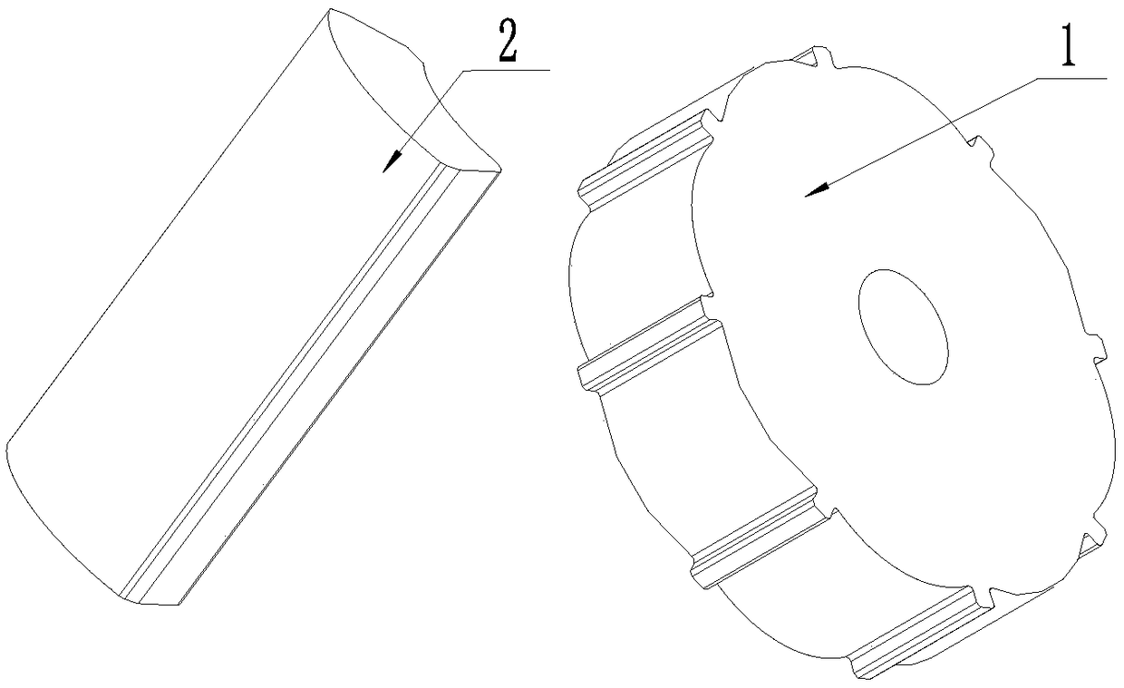
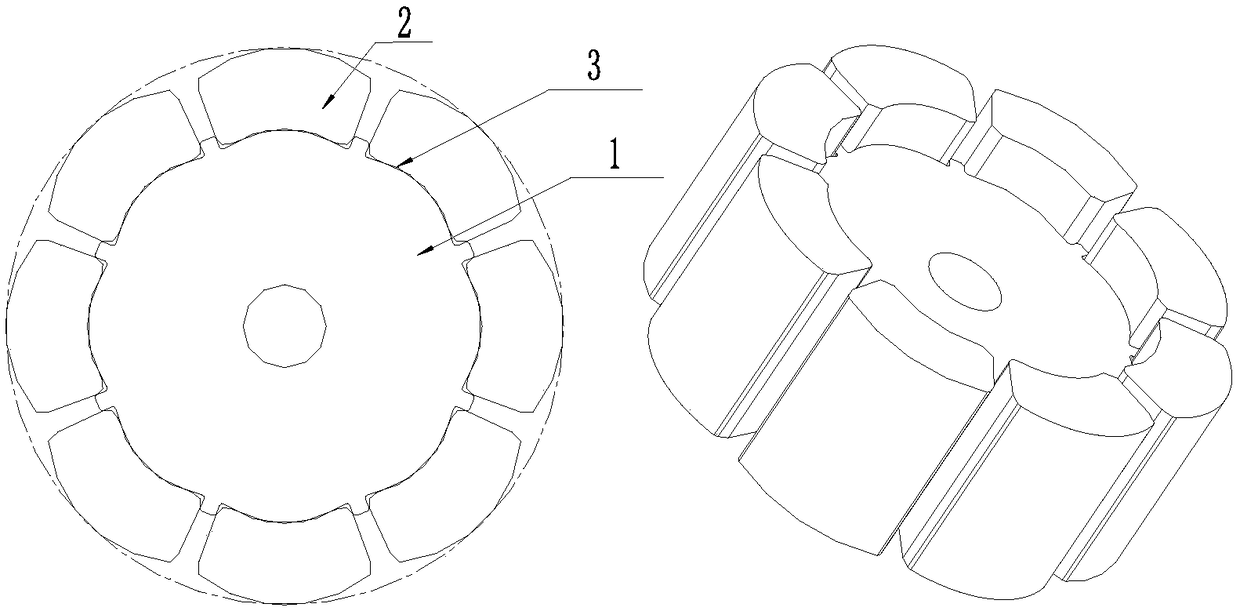
[0062] 1. According to the design requirements, design the corresponding rotor core 1 and magnetic tile 2, wherein the size of the installation groove 31 formed by the teeth of the rotor core is guaranteed to be consistent with the outer contour size of the magnetic tile 2 to meet the assembly requirements;

[0063] 2. Generally, such as Figure 7 As shown, in order to ensure that the magnetic tile 2 can be easily pressed into the installation groove 31 of the rotor core 1, the inner side of the installation groove 31 of the rotor core 1 will be set as an inclined side wall, and the angle A1 is 91 degrees, that is, the side of the installation groove 31 The wall has a slope of 1° from the vertical;

[0064] 3. Generally, such as Figure 8 As shown, in order to ensure the fastening strength between the teeth of the rotor iron core and the magnetic tile 2, the width of the teeth of the rotor iron core L2=(0.6~0.7)*L1, where L1 is the width of the magnetic tile 2;

[0065] 4. I...


PUM


Abstract

The invention provides a rotor structure, a motor rotor and a motor, and relates to the technical field of a DC brushless motor. By the rotor structure, the motor rotor and the motor, the technical problem of high production cost of the rotor structure is solved. The rotor structure comprises an iron core and a magnetic tile, wherein a plug structure is arranged on the iron core and / or the magnetic tile, the magnetic tile can be arranged on the iron core in a plug mode by the plug structure, the magnetic tile is fixedly connected with the iron core in an interference fitting mode, the plug structure is an installation groove formed between two iron core tooth parts and arranged along a circumferential direction of the iron core, the magnetic tile is inserted into the installation groove, the magnetic tile and the installation groove are connected in the interference fitting mode, a side wall of the installation groove is an inclined side wall inclining outwards by 1 degree, so that theinstallation groove which is large in upper part and small in lower part is formed. The rotor structure has the characteristics of low cost, motor running reliability, rotor air gap uniformity, highrotor magnetic field utilization ratio and high motor efficiency, the motor cogging torque and the torque pulse are reduced, and the motor noise performance is improved.

Description

technical field [0001] The invention relates to the technical field of DC brushless motors, in particular to a novel magnetic tile surface-mounted rotor structure, a motor rotor and a motor. Background technique [0002] At present, the rotors used in brushless DC motors include plastic magnetic annular structure rotors, magnetic tile embedded structure rotors and magnetic tile surface-mounted structure rotors. Among them, the existing magnetic tile surface-mounted structure rotor has two structural forms, such as figure 2 As shown, the first magnetic tile surface-mounted rotor is to paste the magnetic tile on the circumferential surface of the rotor core through epoxy glue; as image 3 As shown, the second magnetic tile surface-mounted rotor is made of injection plastic, and the magnetic tile and the rotor core are injected into one body through a mold. [0003] The first type of surface-mounted rotor with epoxy glue has the following defects: 1. The epoxy glue is expensi...

Claims


Application Information

Patent Timeline
Patent Type & Authority Applications(China)
IPC IPC(8): H02K1/27H02K1/28
CPCH02K1/278H02K1/28
Inventor 蔡易霖唐林张驰黄海良纪泽轩李刚刘丽刚
Owner GREE ELECTRIC APPLIANCES INC
Why Eureka
Try Eureka