

Conductive cup processing technology
A processing technology, the technology of circular plate, applied in the field of conductive cup processing technology, can solve the problems of long production cycle, low work efficiency, high production cost, etc., to prolong the service life, reduce friction, ensure surface quality and dimensional accuracy Effect
- Summary
- Abstract
- Description
- Claims
- Application Information
AI Technical Summary
Problems solved by technology
Method used
Image

Examples
Embodiment 1
[0037] Embodiment one: see Figure 2-4 , a kind of processing technology of conductive cup, it comprises the following steps:
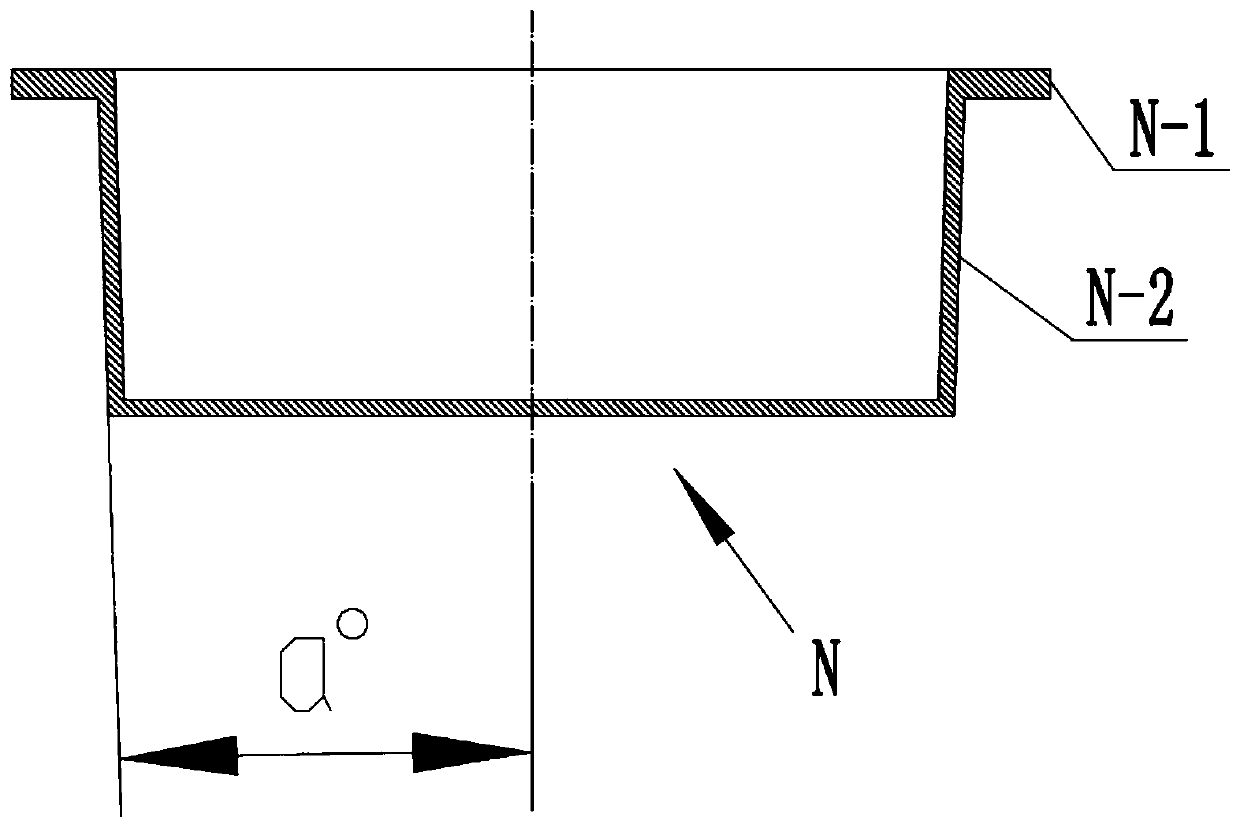
[0038] S10, preparing a circular plate 1 of equal thickness, and the outer diameter of the circular plate 1 is equal to the outer diameter of the flange cover part N-1 of the conductive cup N;
[0039] S20, oiling the two board surfaces of the circular plate 1;
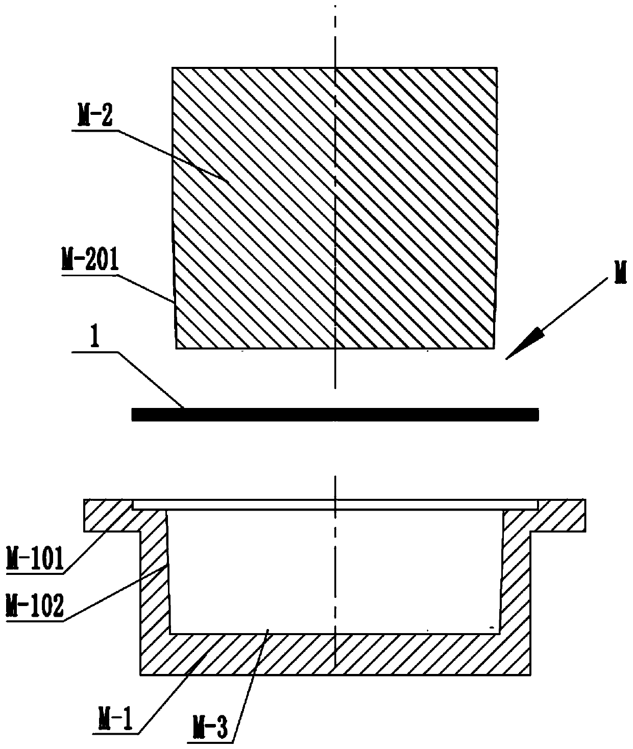
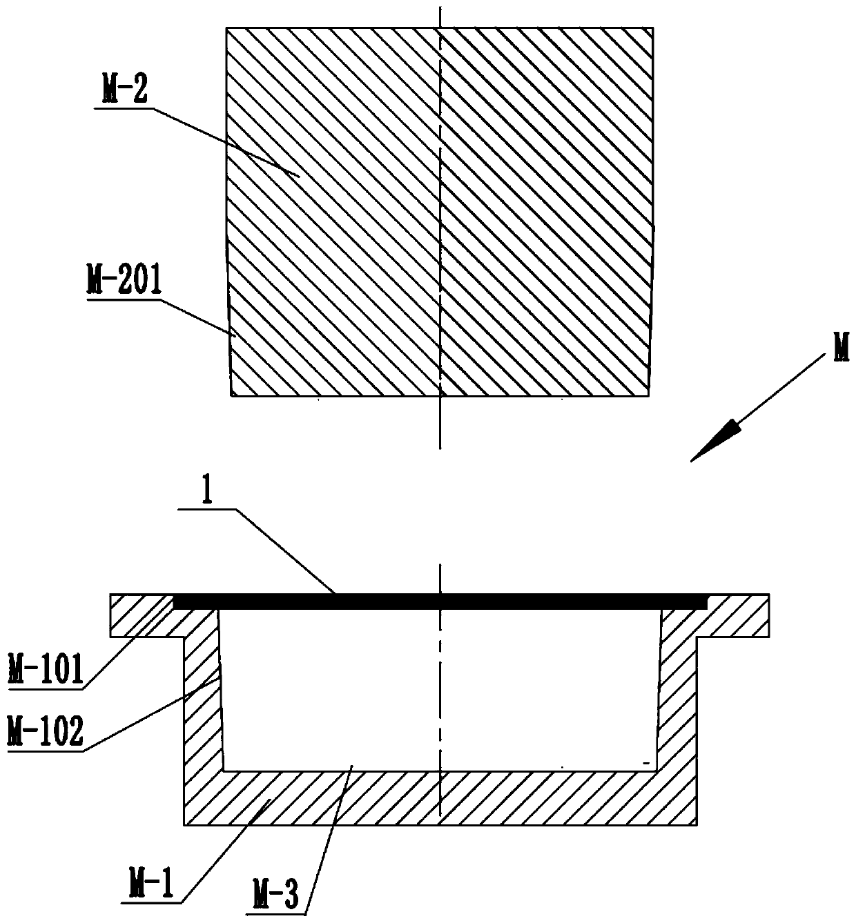
[0040] S30, the circular plate 1 is punched and formed by the stamping die M at one time.
[0041] Using the above-mentioned process method, since the equal-thickness circular plate 1 is prepared first, and the outer diameter of the circular plate 1 is equal to the outer diameter of the flange cover part N-1 of the conductive cup N, the non-stamping part of the outer edge of the circular plate 1 is formed as a conductive The flange cover part N-1 of the cup N does not need to be stretched, and at the same time, the accuracy of the outer dimension and the flatness of the shape of the flange ...
Embodiment 2
[0050] Embodiment two: see Figure 5-7 , a kind of processing technology of conductive cup, it comprises the following steps:
[0051] S10, preparing a circular plate 1 of equal thickness, and the outer diameter of the circular plate 1 is equal to the outer diameter of the flange cover part N-1 of the conductive cup N;
[0052] S20, oiling the two board surfaces of the circular plate 1;
[0053] S30, the circular plate 1 is punched and formed by the stamping die M at one time.
[0054] In this embodiment, the oil is mixed with one or more of paraffin oil, white mineral oil or rapeseed oil.
[0055] Specifically, the circular plate 1 is made of aluminum or iron.
[0056] In this embodiment, the preparation of the equal-thickness circular plate 1 is obtained by plate punching or plate wire cutting. Preferably, it is obtained by punching a plate, which can improve work efficiency.
[0057] Wherein, the stamping die M includes a die M-1 and a punch M-2, and when the punch M-2 i...
Embodiment 3
[0063] Embodiment three: see Figure 8-11 , this embodiment is basically the same as Embodiment 1 and Embodiment 2, the difference lies in that the outer top mechanism 2 of the flange cover part is also provided;
[0064] The flange cover outer ejection mechanism 2 includes a cylinder 2-1, a horizontal push rod 2-2, a vertical push rod 2-3 and a return spring 2-4.
[0065] The bottom end surface of the forming hole section M-101 of the inner flange cover of the die M-1 or the bottom end surface of the upper round hole section M-111 is provided with a push rod matching hole 2-5;
[0066] The middle part of the vertical ejector rod 2-3 is provided with a ring stopper 2-31;
[0067] The ejector rod matching hole 2-5 includes an upper hole section 2-51 and a lower hole section 2-52, and the inner diameter of the upper hole section 2-51 is smaller than the outer diameter of the ring stopper 2-31;
[0068] The upper part of the vertical push rod 2-3 is in clearance fit with the up...
PUM
 Abstract
Description
Claims
Application Information