Slipring unit for a wound rotor motor

A winding, motor technology, applied in asynchronous induction motors, electrical components, rotating current collectors, etc., can solve the problems of troublesome setting and maintenance, and high motor cost

Active Publication Date: 2018-11-23
ABB (SCHWEIZ) AG
View PDF10 Cites 1 Cited by
  • Summary
  • Abstract
  • Description
  • Claims
  • Application Information

AI Technical Summary

Problems solved by technology

This mechanism requires cumbersome set-up

Method used


Image

  • Slipring unit for a wound rotor motor
  • Slipring unit for a wound rotor motor
  • Slipring unit for a wound rotor motor

Examples


Embodiment approach

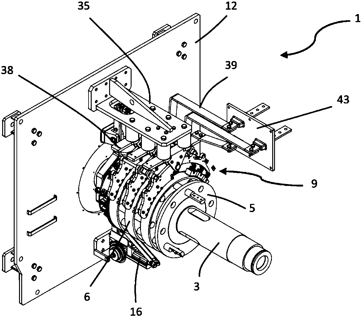
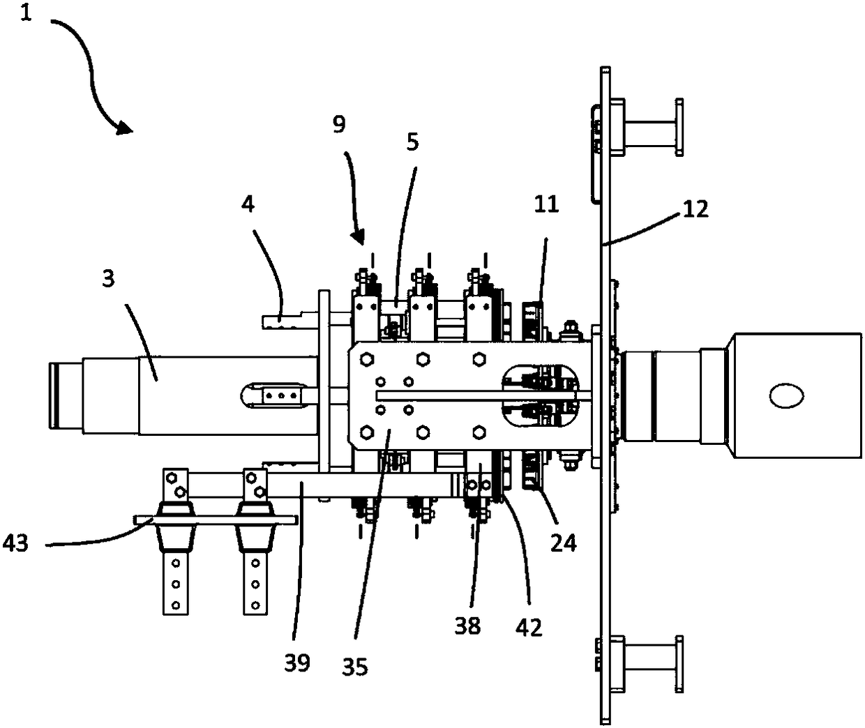
[0053] According to one embodiment, each brush assembly 9 includes a protruding portion 38, which can be, for example, a fixed plate 30 extending transverse to the axial direction of the shaft 3, preferably extending perpendicular to the axial direction of the shaft 3. Part. Still more preferably, the protruding portion 38 extends on both sides of the brush assembly 9. The protruding portion 38 is electrically connected to the brush 10 and electrically insulated from the support frame 35. For example, the protruding portion 38 may be positioned between the insulating spacer 36 and the fixing plate 30, wherein the fixing plate 30, the plate pivot 31, the half plate 29, and the brush holder 32 are made of conductive materials.

[0054] According to a possible embodiment, the actuator 16 is in the upper position (see Figure 7 ), the support frame 35 can also form an actuator plate 46.

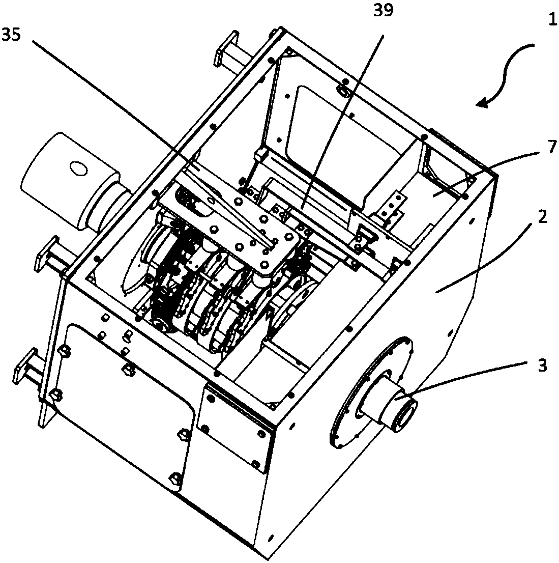
[0055] Advantageously, the unit 1 includes an auxiliary conductive rod 39 for electrically conn...


PUM


Abstract

A slipring unit (1) for a wound rotor motor comprises: - a support plate (12); - a stator; - a rotatable shaft (3); - a ring bushing (5); - one or more brushes assemblies (9), each comprising one or more brushes (10), and a brushes lifting mechanism (21) for moving said one or more brushes (10) between a lowered position; - a short-circuiting bushing (11) integrally rotatable with and slidingly movable relative to the shaft (3) between a short-circuiting position; - at least a main lever (14) hinged to the support plate (12), so to be rotatable relative to the support plate (12) between a first position and a second position.

Description

Technical field [0001] The present invention relates to a slip ring unit for a wound rotor motor (also called a slip ring motor), in particular a slip ring unit with movable brushes. Background technique [0002] A wound rotor motor is a special asynchronous motor that includes a rotatable shaft with a wound rotor core and a ring sleeve which carries a metal ring and is fitted on the shaft. The rotor circuit is connected to an external rheostat to allow the rotor resistance to be changed. For a three-phase motor, the ring sleeve includes three rings, each of which is connected to a single rotor winding phase by a cable. The rotor rotates integrally with the shaft. The slip ring motor also includes three sets of brushes, one set for each phase, and the three sets of brushes are electrically connected to the varistor and electrically insulated from the stator. The brush is in contact with the ring and the brush can be lifted. [0003] When the motor is in a deactivated state, the...

Claims


Application Information

Patent Timeline
IPC IPC(8): H02K13/00
CPCH02K13/003H01R39/08H01R39/42H02K17/22H02K17/30H02K2213/09
Inventor 卡洛·坎波雷亚莱朱塞佩·莫约利
Owner ABB (SCHWEIZ) AG
Why Eureka
Try Eureka