
Piezoelectric motor with variable rotate speed and torque, and use method thereof

A piezoelectric motor and torque technology, which is applied in the direction of piezoelectric effect/electrostrictive or magnetostrictive motors, generators/motors, electrical components, etc. To meet the output requirements and other issues, to achieve the effect of high torque-to-weight ratio

Active Publication Date: 2018-11-23
FUJIAN UNIV OF TECH
View PDF6 Cites 0 Cited by
  • Summary
  • Abstract
  • Description
  • Claims
  • Application Information

AI Technical Summary

Problems solved by technology

[0003] At present, the output torque and speed of the piezoelectric motor are realized by controlling the position between the excitation vibration frequency of the piezoelectric elastic body and the resonance frequency of the elastic body through the control circuit. This speed regulation method leads to a decrease in the overall power of the motor. At the same time as the speed changes, the output torque will become smaller. At this time, the output torque can only be reduced and cannot be increased; thus resulting in failure to meet the output requirements

Method used


Image

  • Piezoelectric motor with variable rotate speed and torque, and use method thereof
  • Piezoelectric motor with variable rotate speed and torque, and use method thereof

Examples


Embodiment 1

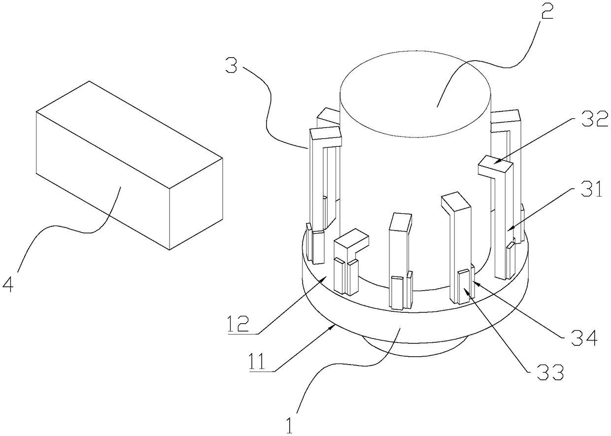
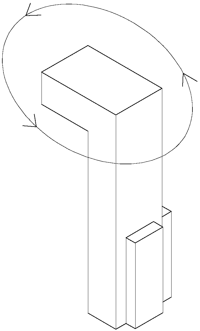
[0024] Such as figure 1 As shown, a piezoelectric motor with variable torque and rotating speed includes an annular stator base 1, the stator base 1 includes a first end face 11 and a second end face 12, and a rotatable rotor 2 is provided in the middle of the stator base 1, The second end surface 11 of the stator seat 1 is provided with a driving part 3, and the driving part 3 is driven by the driver 4. The driving part 3 includes multiple groups of driving legs with different lengths. The number of driving legs in this embodiment is preferably five groups. The number of driving feet in the group is not less than two and the lengths are equal. The driving feet of the same group are evenly arranged along the circumference of the second end face 12. The number of driving feet in this embodiment is preferably two; because the length of the driving feet is different, the resonant frequency Also different, the driving frequency of the driver 4 driving different groups of driving f...

Embodiment 2

[0028] A method for using a piezoelectric motor with variable torque and rotational speed, the method comprising:

[0029] 1) Select the driver that matches the rotor speed

[0030] Introduce the calculation formula of the rotor speed v

[0031] v=f*X qn *60 / 2*3*π*r

[0032] Among them, f is the driving frequency of the driver; X qn is the swing amplitude of each driving foot in the direction perpendicular to the rotor radius, q is the number of groups, n is the number of driving feet of any driving group; rotor radius r;

[0033] According to the above measured parameters and the required rotor speed, the drive frequency f required for the output speed is calculated. Since the frequencies of driving different groups of drive legs are different, the drive legs that meet the drive frequency f can be determined;

[0034] 2) Select the number of driving feet that output the rotor torque

[0035] Introduce the calculation formula of rotor torque

[0036] M=(λ q1 +λ q2 +......


PUM


Abstract

The invention discloses a piezoelectric motor with variable torque and rotate speed. The piezoelectric motor with variable torque and rotate speed comprises a ring-shaped stator seat; the stator seatcomprises a first end surface and a second end surface; the middle part of the stator seat is provided with a rotatable rotor; the second end surface of the stator seat is provided with a driving part; the driving part is driven by a driver; the driving part comprises plurality groups of driving feet with different heights, the number of any one group of the driving feet is not less than two and the lengths are equal, and the driving feet of the same group are uniformly arranged along the circumferential direction of the second end surface; and the driver drives different groups of driving feet with different driving frequencies. The piezoelectric motor disclosed by the invention comprises plurality groups of driving feet with different heights, and the driver drives each group of the driving feet at different driving frequencies, therefore, different output rotate speeds can be provided; in addition, the number of each group of the driving feet is not less than two, and the driving feet group with different number can provide different output torques, therefore, the shortcoming of electromagnetic motors that can not achieve low speed and high torque output is overcome; and the piezoelectric motor disclosed by the invention has the characteristics of no electromagnetic pollution, high torque-to-weight ratio and the like.

Description

technical field [0001] The invention relates to the technical field of industrial control systems, in particular to a piezoelectric motor with variable speed and torque and a use method thereof. Background technique [0002] Piezoelectric motors use the inverse piezoelectric effect of ceramics. By applying voltage to piezoelectric ceramics, piezoelectric ceramics vibrate, which in turn excites the stator of the motor to vibrate and drives the rotor to move. [0003] At present, the output torque and speed of the piezoelectric motor are realized by controlling the position between the excitation vibration frequency of the piezoelectric elastic body and the resonance frequency of the elastic body through the control circuit. This speed regulation method leads to a decrease in the overall power of the motor. At the same time as the speed changes, the output torque will become smaller. At this time, the output torque can only be reduced and cannot be increased; thus resulting in...

Claims


Application Information

Patent Timeline
Patent Type & Authority Applications(China)
IPC IPC(8): H02N2/12H02N2/14
CPCH02N2/12H02N2/142
Inventor 郑伟周景亮余罗兼彭晋民黄伟彬
Owner FUJIAN UNIV OF TECH
Learn More