Multi-motor parallel drive type electric joint and mechanical arm thereof

A driven, multi-motor technology, applied in the direction of manipulators, manufacturing tools, joints, etc., can solve the problem of low torque-to-weight ratio of electric joints, and achieve the effect of reducing volume and weight and high torque-to-weight ratio

Pending Publication Date: 2017-07-04
保定市恒信达电气有限公司
View PDF6 Cites 4 Cited by
  • Summary
  • Abstract
  • Description
  • Claims
  • Application Information

AI Technical Summary

Problems solved by technology

[0004] The purpose of the present invention is to provide a multi-motor parallel driven electric joint to solve the problem of low torque-to-weight ratio of existing electric joints

Method used


Image

  • Multi-motor parallel drive type electric joint and mechanical arm thereof
  • Multi-motor parallel drive type electric joint and mechanical arm thereof
  • Multi-motor parallel drive type electric joint and mechanical arm thereof

Examples


Embodiment Construction

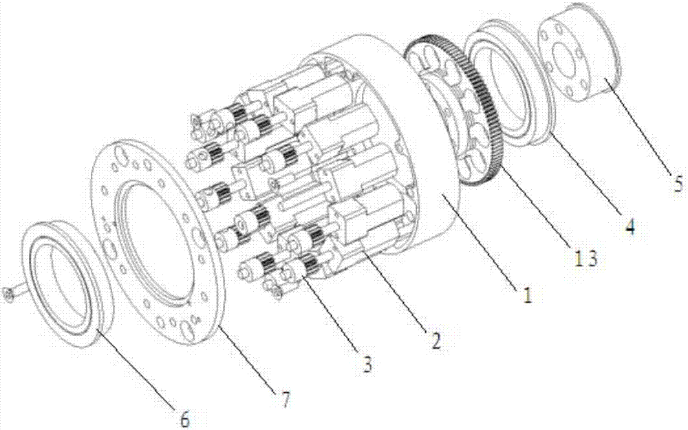
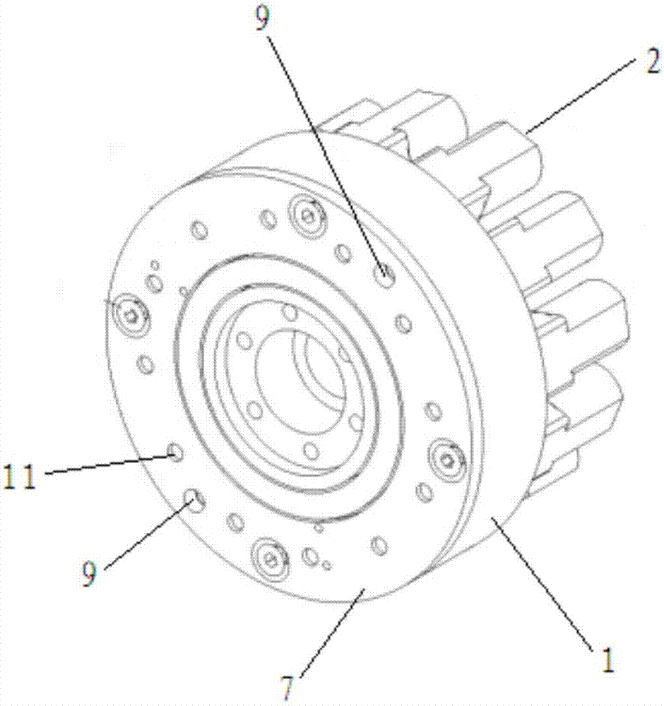
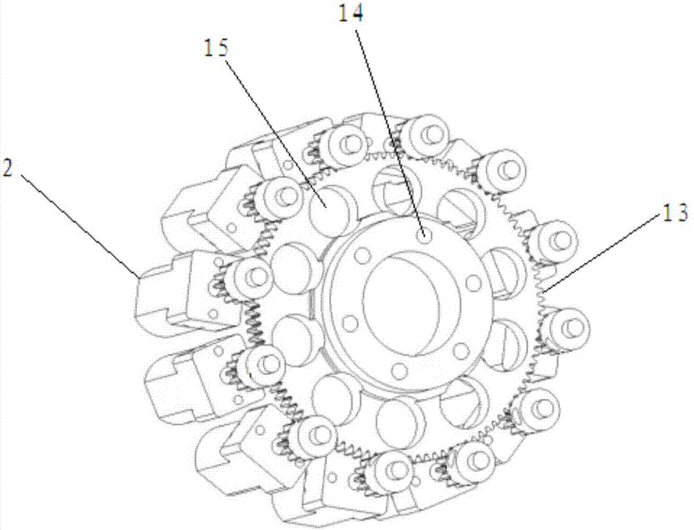
[0036] Such as figure 1 As shown, one specific embodiment of a multi-motor parallel-driven electric joint includes a motor fixing plate 1, a motor 2, a driving gear 3, a support bearing 4, a support bearing fixing block 5, an output bearing 6, and an output bearing fixing Plate 7 and output gear 13.

[0037] Such as Figure 1-8 As shown, the motor is mounted on the motor fixing plate. Specifically, the motor fixing plate 1 includes a base 101 , a bearing mounting hole 102 , a motor shaft through hole 103 , a motor fixing hole 104 , a connecting hole 105 and a mounting hole 106 . The base body 101 is disc-shaped with sidewalls. The bearing installation hole 102 is opened at the center of the bottom surface of the base body 101 , and the support bearing 4 is installed in the bearing installation hole 102 . More specifically, the outer ring of the support bearing 4 is clamped in the bearing installation hole 102 , and the inner ring is clamped with the support bearing fixing b...


PUM


Abstract

The invention discloses a multi-motor parallel drive type electric joint, which comprises a motor fixing plate, motors, drive gears, a support bearing, a supporting bearing fixing block, an output bearing, an output bearing fixing plate and an output gear. The motors are fixed onto the motor fixing plate; the motor fixing plate comprises a base body, a bearing installing hole, motor shaft through holes, motor fixing holes, connecting holes and installing holes; the plurality of motors are used for providing operation power; the drive gears are arranged on rotary shafts of the motors; the support bearing is arranged in the bearing installing hole. According to the multi-motor parallel drive type electric joint provided by the invention, through increasing the number of meshing gears, the aim of enabling the output gear to be stressed uniformly is achieved; by utilizing the self-flexibility of the motors, the effects on cooperative work and collaboration of a plurality of gear sets are realized, the volume and the weight of an electric joint reducing mechanism are greatly reduced, and higher torque weight ratio can be obtained under common machining precision.

Description

technical field [0001] The invention relates to the field of electric joints, in particular to a multi-motor parallel driven electric joint and a manipulator thereof. Background technique [0002] The electric joint is an electric device used in robots and manipulators. Its function is to output torque and control the rotation angle of the machine. It is generally composed of motors, transmission gears, and control circuits. The performance of electric joints has a great influence on robots and manipulators. The greater the torque-to-weight ratio of electric joints, the lighter the structure weight of robots and manipulators. Electric joints with high torque-to-weight ratios are essential components of high-performance robots. [0003] Existing electric joints are generally driven by a single motor, and the speed of the motor is reduced and the torque is amplified through a planetary reducer, a harmonic reducer, a cycloidal reducer, etc., and a larger output torque and mecha...

Claims


Application Information

Patent Timeline
Patent Type & Authority Applications(China)
IPC IPC(8): B25J17/02
CPCB25J17/0266
Inventor 李娟
Owner 保定市恒信达电气有限公司
Why Eureka
Try Eureka