Apparatus, method and receiver for estimating linear crosstalk between channels

An inter-channel, linear technology, applied in the field of communication, can solve the problem that the magnitude of linear crosstalk cannot be estimated concretely

Active Publication Date: 2021-04-13
FUJITSU LTD
View PDF6 Cites 0 Cited by
  • Summary
  • Abstract
  • Description
  • Claims
  • Application Information

AI Technical Summary

Problems solved by technology

Another example, non-patent literature [2] or US patent (US20140314415 A1) proposes to use frequency offset to select subcarrier frequency bands, thereby reducing the impact of linear crosstalk, but this method can only roughly estimate the The range of overlapping between carriers cannot specifically estimate the size of linear crosstalk

Method used


Image

  • Apparatus, method and receiver for estimating linear crosstalk between channels
  • Apparatus, method and receiver for estimating linear crosstalk between channels
  • Apparatus, method and receiver for estimating linear crosstalk between channels

Examples


Embodiment 1

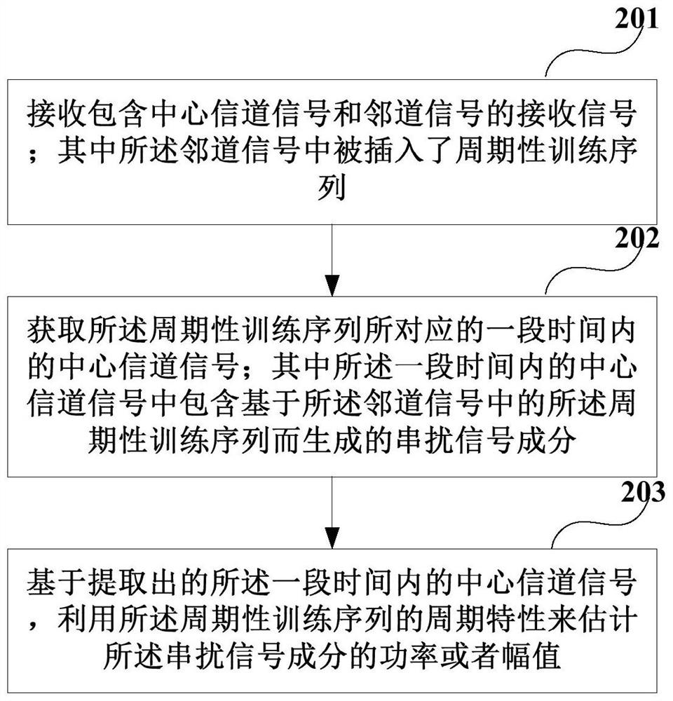
[0049] An embodiment of the present invention provides a method for estimating linear crosstalk between channels. figure 2 It is a schematic diagram of a method for estimating inter-channel linear crosstalk according to an embodiment of the present invention, and is described from the receiver side. Such as figure 2 As shown, the method includes:

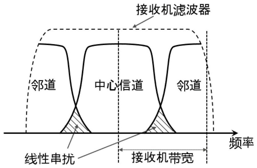
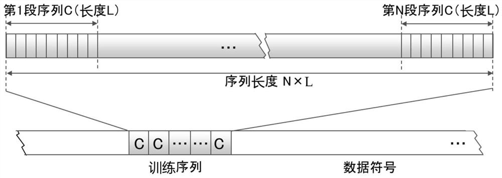
[0050] Step 201, receiving a received signal including a central channel signal and an adjacent channel signal; wherein a periodic training sequence is inserted into the adjacent channel signal;

[0051] Step 202, acquiring the center channel signal within a period of time corresponding to the periodic training sequence; wherein the center channel signal within a period of time includes a signal generated based on the periodical training sequence in the adjacent channel signal crosstalk signal components;

[0052] Step 203: Estimate the power or amplitude of the crosstalk signal component by using the period characteristic of t...

Embodiment 2

[0086] An embodiment of the present invention provides a device for estimating linear crosstalk between channels, which can be configured in a receiver. This embodiment of the present invention corresponds to the estimation method in Embodiment 1, and the same content will not be described again.

[0087] Figure 8 is a schematic diagram of an estimation device for inter-channel linear crosstalk according to an embodiment of the present invention, as shown in Figure 8 As shown, the estimation apparatus 800 of linear crosstalk between channels includes:

[0088] A signal receiving unit 801, which receives a received signal including a central channel signal and an adjacent channel signal; wherein a periodic training sequence is inserted into the adjacent channel signal;

[0089] A signal extraction unit 802, which acquires a central channel signal within a period of time corresponding to the periodic training sequence; wherein the central channel signal within a period of ti...

Embodiment 3

[0111] An embodiment of the present invention provides a receiver, which can be configured with the apparatus 800 for estimating inter-channel linear crosstalk as described in Embodiment 2; the content that is the same as that of Embodiments 1 and 2 in this embodiment of the present invention will not be repeated here. The following will take an optical receiver in an optical communication system as an example for description, but the present invention is not limited thereto.

[0112] Figure 13 is a schematic diagram of the receiver of the embodiment of the present invention, such as Figure 13 As shown, the receiver 1300 may include:

[0113] A photoelectric converter 1301, which converts the received optical signal into an electrical signal;

[0114] A digital signal processor 1302, which receives a received signal including a center channel signal and an adjacent channel signal; wherein a periodic training sequence is inserted into the adjacent channel signal; and obtain...


PUM


Abstract

Embodiments of the present invention provide a device, method and receiver for estimating linear crosstalk between channels. The method includes: receiving a received signal including a central channel signal and an adjacent channel signal, wherein a periodic training sequence is inserted into the adjacent channel signal; acquiring the central channel signal within a period of time corresponding to the periodic training sequence ; Based on the extracted central channel signal within a period of time, use the period characteristic of the periodic training sequence to estimate the power or amplitude of the crosstalk signal component. Therefore, the linear crosstalk between channels can be accurately and effectively estimated.

Description

technical field [0001] Embodiments of the present invention relate to communication technologies, and in particular to an estimation device, method and receiver for linear crosstalk between channels. Background technique [0002] The optical communication system occupies an important position in the communication transmission network due to the advantages of huge transmission bandwidth, extremely low transmission loss and low cost. In order to further increase communication capacity, Dense Wavelength Division Multiplexing (DWDM, DenseWavelength Division Multiplexing) technology is widely used in optical fiber communication systems. [0003] However, while the dense carrier multiplexing scheme doubles the transmission capacity, it compresses the guard interval between channels to a large extent, and inevitably introduces linear crosstalk between channels, causing damage to effective signals. , which limits the transmission performance of the system. Therefore, in a typical ...

Claims


Application Information

Patent Timeline
Patent Type & Authority Patents(China)
IPC IPC(8): H04B17/345H04B1/16
CPCH04B1/16H04B17/345
Inventor 宿晓飞赵颖陶振宁
Owner FUJITSU LTD
Why Eureka
Try Eureka