Estimation method of azimuth difference of digital surface model based on 3d‑zernike moment phase analysis

A technology of digital surface model and azimuth difference, applied in three-dimensional shape analysis and application of remote sensing ground objects, three-dimensional data registration of remote sensing ground objects, and change detection, to achieve excellent robustness.

Active Publication Date: 2017-08-25
HARBIN INST OF TECH
View PDF1 Cites 0 Cited by
  • Summary
  • Abstract
  • Description
  • Claims
  • Application Information

AI Technical Summary

Problems solved by technology

[0005] In order to solve the problem of estimating the azimuth difference between multi-temporal DSMs of ground objects, the present invention proposes a method for estimating the azimuth difference of digital surface models based on 3D-Zernike moments

Method used


Image

  • Estimation method of azimuth difference of digital surface model based on 3d‑zernike moment phase analysis
  • Estimation method of azimuth difference of digital surface model based on 3d‑zernike moment phase analysis
  • Estimation method of azimuth difference of digital surface model based on 3d‑zernike moment phase analysis

Examples


specific Embodiment approach 1

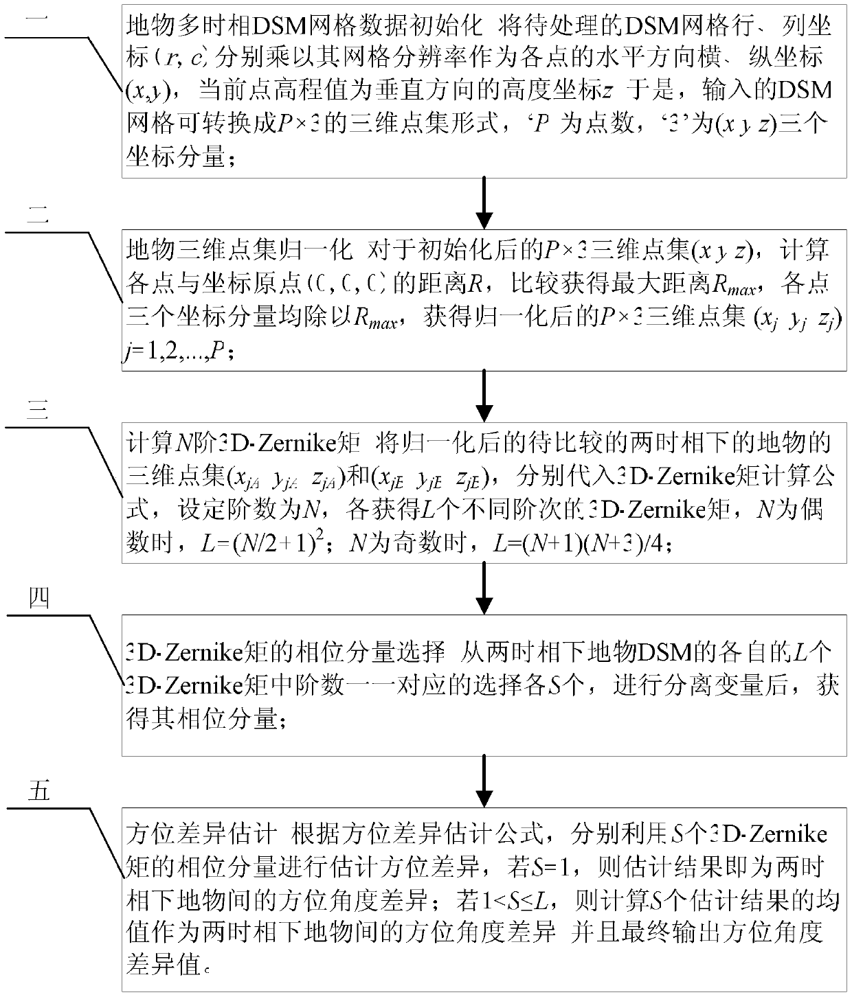
[0038] Specific implementation mode one: combine figure 1 Describe this embodiment, the implementation process of the digital surface model orientation difference estimation method based on 3D-Zernike moment phase analysis described in this embodiment is:

[0039] Step 1. Initialize the multi-temporal DSM grid data of ground objects and standardize the input data format: Multiply the row and column coordinates (r, c) of the DSM grid to be processed by their grid resolution respectively as the horizontal horizontal and horizontal directions of each point. Ordinate (x, y), the elevation value of the current point is the height coordinate z in the vertical direction; thus, the input DSM grid can be converted into a P×3 three-dimensional point set form, 'P' is the number of points, and '3' is ( x, y, z) three coordinate components;

[0040] DSM grid data initialization is as formula (1):

[0041]

[0042]Among them, r and c are the row and column coordinates of DSM, DSM(r, c)...

specific Embodiment approach 2

[0048] Embodiment 2: The difference between this embodiment and Embodiment 1 is that the three-dimensional data normalization method in step 2 can be a calculation method or a custom maximum distance method.

[0049] Calculation method: the distance R formula in step 2 can be calculated as formula (2):

[0050]

[0051] The calculated distance R can be compared and sorted to obtain R max value;

[0052] The normalization formula is as formula (3):

[0053]

[0054] Custom maximum distance method: according to the input DSM data, a uniform maximum distance value R can be set for the DSM data of all ground objects max Carry out the normalization processing of each object DSM, but R max It is necessary to make the three-dimensional point set (x j ,y j ,z j )j=1,2,...,P data are in the unit sphere to meet the calculation requirements of 3D-Zernike moments.

[0055] Other steps are the same as in the first embodiment.

specific Embodiment approach 3

[0056] Specific embodiment three: the digital surface model orientation difference estimation method based on 3D-Zernike moment phase analysis described in the present embodiment, the 3D-Zernike moment numerical calculation formula in step 3 is as formula (4):

[0057]

[0058] Formula (4) is a simplified numerical calculation method derived from the original definition of 3D-Zernike moments, where n∈[0,N],l∈[0,n],m∈[-l,l],k=( n-l) / 2 and must be an integer, this is the order condition of the N-order 3D-Zernike moment, each {n,l,m} combination that satisfies the order condition corresponds to a specific order 3D-Zernike moment j=1,2,...,P, is the serial number of P three-dimensional points; for DSM data, usually set N<5;

[0059] In formula (4), the orthogonalization coefficient The calculation formula is as formula (5):

[0060]

[0061] In formula (4), the harmonic function part The calculation formula is as formula (6):

[0062]

[0063] Where i is the imagin...


PUM


Abstract

The invention discloses a method for estimating a direction variation of digital surface models (DSMs) based on 3D-Zernike (three-dimensional-Zernike) moment phase analysis, relates to the field of surface feature remote sensing analysis, and solves problems that the disunity of definitions of coordinate systems of the multi-temporal DSMs causes the direction variation of surface feature 3D data and difference in height accuracy and resolution enables the direction variation to be unlikely to be estimated, so that the direction variation cannot be effectively applied. The method comprises the following steps: initializing grid data of the surface feature multi-temporal DSMs and standardizing an input data format; normalizing a surface feature 3D point set and normalizing the data to a unit ball body required for 3D-Zernike calculation; calculating N-order 3D-Zernike moments; selecting phase components of the 3D-Zernike moments; estimating the direction variation. The method can accurately judge the direction variation of the surface feature multi-temporal DSMs and is favorable for important remote sensing applications of surface features to multiple aspects of attitude estimation, 3D change detection, earthquake disaster evaluation and the like.

Description

technical field [0001] The invention relates to the field of three-dimensional form analysis and application of remotely sensed ground surface objects, and belongs to the technical field of three-dimensional data registration and change detection of remote sensed ground objects. Background technique [0002] The analysis of remote sensing surface features has always been an important application field of remote sensing information. Typical 3D products of the surface are mainly digital terrain models and various derived data types, among which digital elevation model (Digital Elevation Model, DEM) and digital surface model (Digital Surface Model, DSM) are relatively more well-known . DEM usually only reflects the elevation information of the surface terrain, while DSM can include the elevation information of various typical features, such as buildings and vegetation. With the development of airborne lidar-based technology, it is no longer a technical problem to obtain multi...

Claims


Application Information

Patent Timeline
Patent Type & Authority Patents(China)
IPC IPC(8): G06T7/00G06T7/33
Inventor 闫奕名高凤娇张晔沈毅
Owner HARBIN INST OF TECH
Why Eureka
Try Eureka