

Clock synchronization method and device
A clock synchronization and clock technology, applied in the field of communication, can solve the problem of inaccurate clock synchronization of multi-lane interfaces
- Summary
- Abstract
- Description
- Claims
- Application Information
AI Technical Summary
Problems solved by technology
Method used
Image

Examples
Embodiment 1
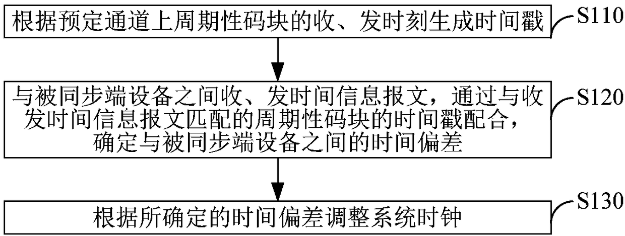
[0090] Embodiment 1. A clock synchronization method, such as figure 1 As shown, including steps S110-S120:
[0091] S110. The synchronization terminal device generates a time stamp according to the receiving and sending time of the aligned code block on the predetermined channel;
[0092] S120. The synchronization terminal device and the synchronized terminal device receive and send time information messages, and determine the time between the synchronized terminal device and the synchronized terminal device through the time stamp of the aligned code block that matches the receiving and sending time information message deviation;
[0093] S130. The synchronization end device adjusts the system clock according to the determined time offset.
[0094] Wherein, the synchronizing terminal device may refer to a device to be synchronized with the synchronized terminal device, and the synchronized terminal device may refer to a device with a clock as a reference standard for synchro...
Embodiment 2
[0120] Embodiment 2, a method for clock synchronization, applied to equipment including multiple time counting systems, the multiple time counting systems are divided into a master time counting system and a slave time counting system; the method is as follows figure 2 As shown, including steps S210-S220:
[0121] S210. Obtain a common divisor from the clock frequency of the main time counting system according to the master time counting system, and create a common divisor clock with the common divisor as the clock frequency;
[0122] S220. Synchronize the common denominator clock with the clock of the master time counting system, and synchronize the clock of the slave time counting system with the common denominator clock.
[0123] In this embodiment, the clock frequency of the time counting system used for timestamping is related to the interface rate, different rate interfaces correspond to time counting systems at different clock frequencies, and each time counting system...
Embodiment 3
[0135] Embodiment 3. A clock synchronization method. In this embodiment, the periodic code block adopts the alignment code block AM, and the clock synchronization process includes the following steps S310-S370:
[0136] Step S310, frequency synchronization.
[0137] Synchronize the frequency of the system clock of the synchronizing end device and the synchronized end device. .
[0138] Step S320, generating a time stamp.
[0139] Detect the alignment code block AM of the specified lane in the sending and receiving direction, record its sending or arrival time, and generate a timestamp.
[0140] The time stamp may be generated by a time counting system corresponding to the aligned code block; wherein, the time counting system corresponding to the aligned code block may include an interface parallel clock (that is, a clock corresponding to the interface parallel data) and a time counter.
[0141] In step S330, the system clock and the interface parallel clock are phase-identi...
PUM
 Abstract
Description
Claims
Application Information