Common mode choke coil

A common mode choke coil and coil technology, applied in the direction of transformer/inductor coil/winding/connection, inductor, inductor with magnetic core, etc., can solve the problems of expanding the core 101, unable to reduce the invalid area, etc. Achieve the effect of increasing the cross-sectional area and increasing the L value

Active Publication Date: 2018-11-23
MURATA MFG CO LTD
View PDF7 Cites 4 Cited by
  • Summary
  • Abstract
  • Description
  • Claims
  • Application Information

AI Technical Summary

Problems solved by technology

[0006] However, if the core portion 101 is expanded radially outward, the core portion 101 cannot be expanded radially outward due to restrictions on the external dimensions of the coil component 100 .
[0007] On the other hand, if the core portion 101 is to be expanded radially inward, the inner wire member 111 of the first coil 110 and the inner wire member 121 of the second coil 120 are in circumferential contact, and the core portion 101 cannot be expanded radially inward.
In other words, if the inner diameter of the core 101 is made small, the inner wire member 111 of the first coil 110 and the inner wire member 121 of the second coil 120 will contact in the circumferential direction, and the dead zone D cannot be reduced.

Method used


Image

  • Common mode choke coil
  • Common mode choke coil
  • Common mode choke coil

Examples


no. 1 approach

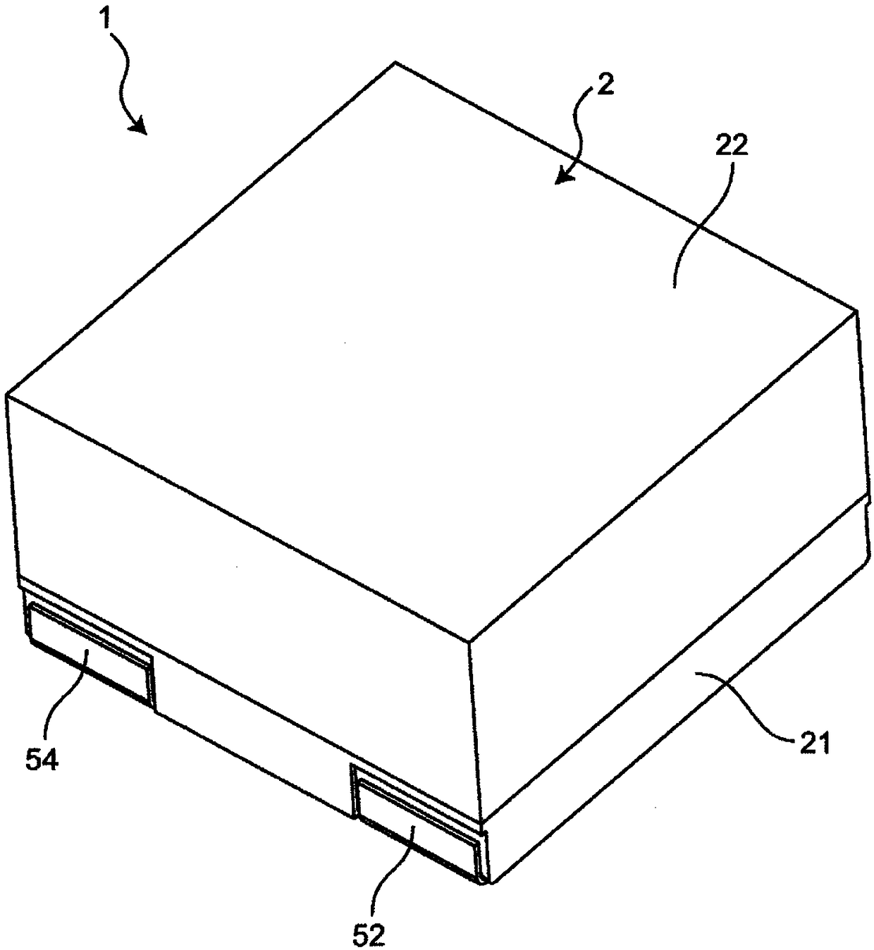
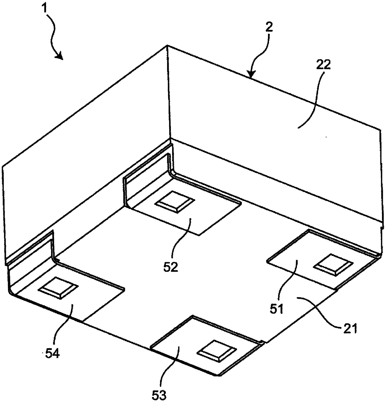
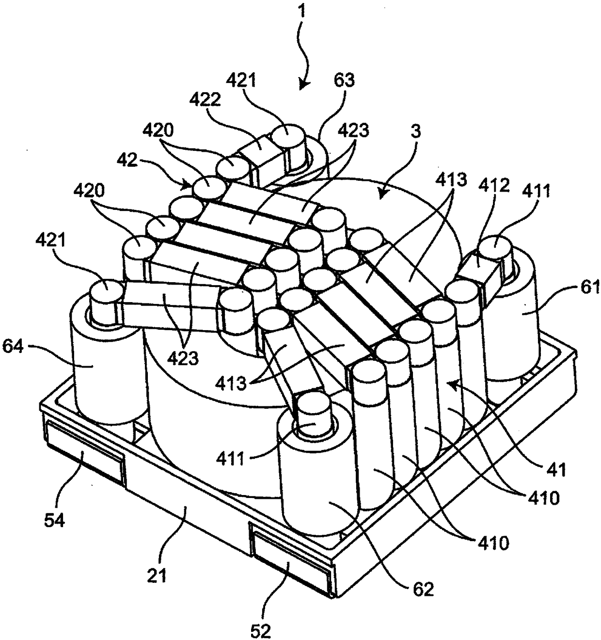
[0052] figure 1 It is an upper perspective view showing the common mode choke coil according to the first embodiment of the present invention. figure 2 It is the bottom perspective view of the common mode choke coil. image 3 It is an upper perspective view showing the inside of the common mode choke coil. Figure 4 It is an exploded perspective view of a common mode choke coil. Figure 5 is a top view of the common mode choke coil.

[0053] Such as Figure 1 to Figure 5 As shown, the common mode choke coil 1 has: a housing 2; an annular core 3 accommodated in the housing 2; a first coil 41 and a second coil 42 wound around the core 3 facing each other; and First to fourth ferrite beads 61 to 64 attached to the first coil 41 and the second coil 42 .

[0054] The housing 2 has a bottom plate portion 21 and a box-shaped cover portion 22 covering the bottom plate portion 21 . The casing 2 is made of, for example, resin such as PPS or ceramics. The core portion 3 is provi...

no. 2 approach

[0123] Figure 7 It is a plan view showing the second embodiment of the common mode choke coil of the present invention. The second embodiment differs from the first embodiment in the shape of the casing. This different configuration will be described below. In addition, in 2nd Embodiment, the same code|symbol as 1st Embodiment is the same structure as 1st Embodiment, Therefore The description is abbreviate|omitted.

[0124] like Figure 7 As shown, the shape of the casing 2A is rectangular when viewed from the direction of the central axis C of the core 3 . The shape of the core 3 is an elongated shape (in this embodiment, an oblong shape) as viewed from the direction of the central axis C of the core 3 . The core 3 is accommodated in the case 2A, and the direction of the major axis L of the core 3 is the same as the direction of the major axis of the case 2A. also, Figure 7 In , the drawing of coils and ferrite beads is omitted.

[0125] Therefore, since the core 3 i...


PUM

PropertyMeasurementUnit
thicknessaaaaaaaaaa

Abstract

A common mode choke coil comprises a ring-shaped core, and a first coil and a second coil which are wound on the core so as to oppose each other. The core has a square shape or a rectangular shape having a major axis and a minor axis, as viewed in a central axis direction of the core. The first coil and the second coil each comprise a single-layer winding. The area of a lateral section perpendicular to the circumferential direction of the core is constant along the circumferential direction of the core. The shape of the lateral section of the core is quadrilateral.

Description

technical field [0001] The invention relates to a common mode choke coil. Background technique [0002] Conventionally, as a coil component, what is described in Unexamined-Japanese-Patent No. 2006-165212 (patent document 1) is known. like Figure 8 As shown, the coil component 100 has an annular core 101 , and a first coil 110 and a second coil 120 wound around the core 101 so as to face each other. The first coil 110 and the second coil 120 have: inner wire members 111, 121 located in the inner diameter hole of the core 101; outer wire members 112, 122 located radially outside of the core 101; and the inner wire members 111, 122 121 is the wiring 113 , 123 connected to the outer wire member 112 , 122 . [0003] Patent Document 1: Japanese Patent Laid-Open No. 2006-165212 [0004] However, in the above conventional coil component 100, if the inner wire member 111 of the first coil 110 and the inner wire member 121 of the second coil 120 are arranged along the inner perip...

Claims


Application Information

Patent Timeline
Patent Type & Authority Applications(China)
IPC IPC(8): H01F17/06H01F27/28
CPCH01F17/062H01F27/28H01F27/306H01F27/2828H01F27/292H01F2017/0093H01F27/02H01F27/2823H01F27/24H01F27/29
Inventor 佐佐木达哉平井真哉长谷川信
Owner MURATA MFG CO LTD
Why Eureka
Try Eureka