
Vacuum cleaner and comb tooth structure thereof

A comb-tooth structure and technology for vacuum cleaners, applied in vacuum cleaners, suction nozzles, cleaning equipment, etc., can solve the problems of easy blockage of suction ports and easy accumulation of dust in air ducts, so as to avoid clogging of garbage, smooth air intake, and increase air intake. area effect

Pending Publication Date: 2018-11-27
SKYBEST ELECTRIC APPLIANCE SUZHOU CO LTD
View PDF0 Cites 2 Cited by
  • Summary
  • Abstract
  • Description
  • Claims
  • Application Information

AI Technical Summary

Problems solved by technology

[0004] The purpose of the present invention is to provide a vacuum cleaner comb structure and a vacuum cleaner to solve the technical problems existing in the prior art that dust is easy to accumulate on both sides of the air duct and the suction port is easy to be blocked.

Method used


Image

  • Vacuum cleaner and comb tooth structure thereof
  • Vacuum cleaner and comb tooth structure thereof
  • Vacuum cleaner and comb tooth structure thereof

Examples


Embodiment Construction

[0028] In order to make the technical problems solved by the present invention, the technical solutions adopted and the technical effects achieved clearer, the technical solutions of the present invention will be further described below in conjunction with the accompanying drawings and through specific implementation methods. It should be understood that the specific embodiments described here are only used to explain the present invention, but not to limit the present invention. In addition, it should be noted that, for the convenience of description, only the parts related to the present invention are shown in the drawings but not all of them.

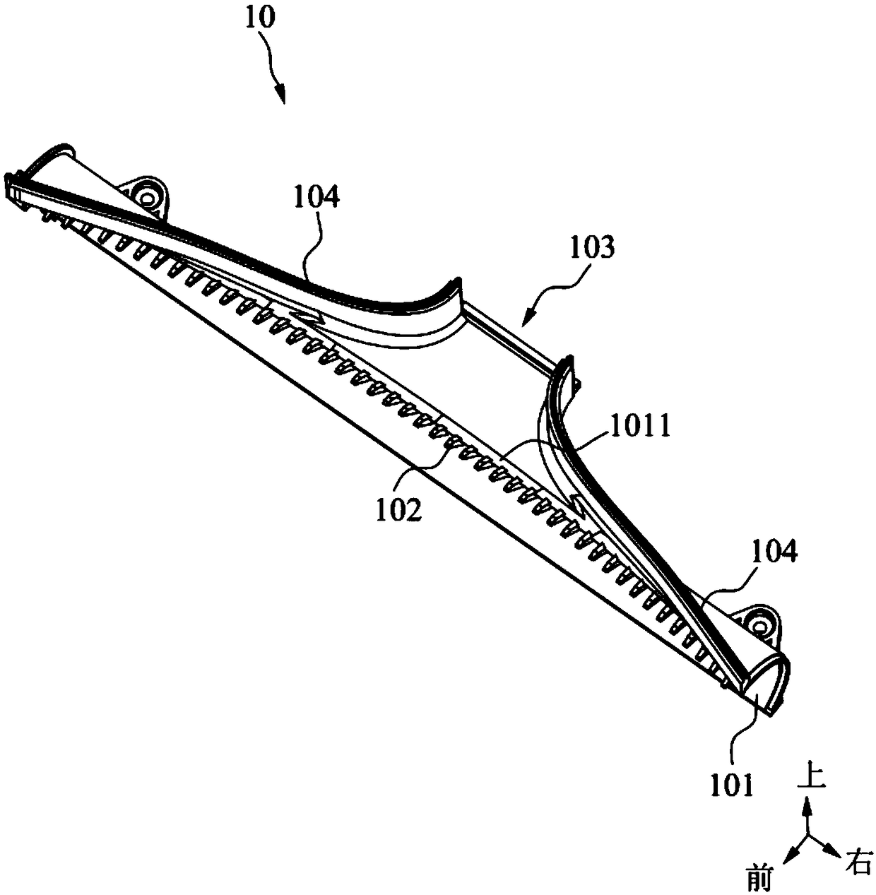
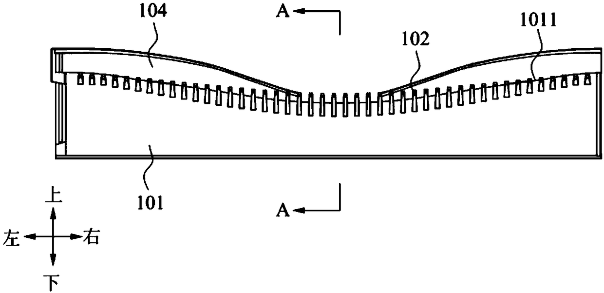
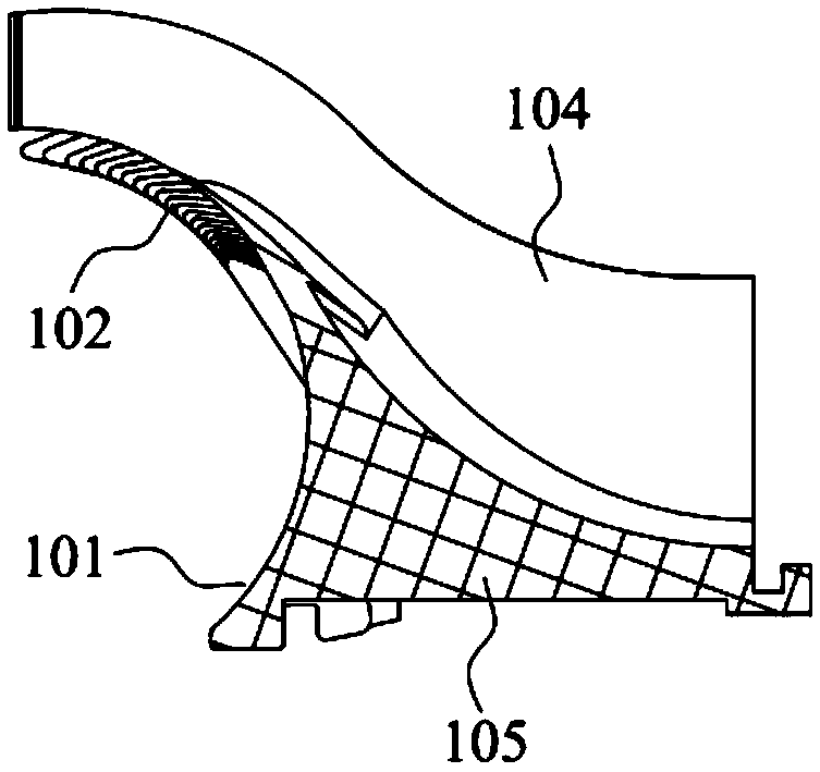
[0029] see figure 1 and figure 2 , the embodiment of the present invention provides a vacuum cleaner comb structure, which is installed on the outside of the vacuum cleaner's roller brush, which can not only peel off the dust on the vacuum cleaner's roller brush, but also guide the wind so that the dust can enter the air outlet 103...


PUM


Abstract

The invention discloses a vacuum cleaner and a comb tooth structure thereof. The comb tooth structure includes a base portion, a plurality of comb teeth arranged on the base portion parallelly at intervals and an air outlet formed in rear of the comb teeth. The base portion is provided with an arc surface for fitting a roller brush; all the comb teeth are arranged on the upper edge of the arc surface; the upper edge of the arc surface is recessed from its two ends to the middle; the arrangement of the comb teeth along the upper edge has an outline that is recessed from its two ends to the middle. The vacuum cleaner includes the above comb tooth structure. The base portion cooperates with the comb teeth so that it is convenient to guide dust on two sides of an air passage and dust removed by the comb teeth to the air outlet, thereby preventing dust accumulation in the air passage; the air passage is gathered in flat form from the disperse sides to the center smoothly so that incoming air is smooth and waste jamming is avoided; vacuum loss is reduced so that intake area of the air passage is enlarged; therefore, dust-holding capacity of the air passage is increased, and the air inletof the air passage is rarely jammed.

Description

technical field [0001] The invention relates to the technical field of cleaning equipment, in particular to a vacuum cleaner comb structure and a vacuum cleaner. Background technique [0002] Vacuum cleaners are common cleaning tools. The cleaning principle of vacuum cleaners is to suck dust and dry debris, such as threads, paper scraps, hair, etc., from floors, carpets, walls, furniture and other surfaces by means of suction. [0003] A roller brush is arranged inside the vacuum cleaner, and the rotation of the roller brush facilitates bringing sundries into the air duct. However, during the use of the vacuum cleaner, dust will accumulate on both sides of the air duct or the suction port will be blocked, which is not convenient for cleaning and affects the normal use of the vacuum cleaner. Contents of the invention [0004] The purpose of the present invention is to provide a vacuum cleaner comb structure and a vacuum cleaner to solve the technical problems existing in t...

Claims


Application Information

Patent Timeline
IPC IPC(8): A47L9/04
CPCA47L9/0461
Inventor 刘海平邢振宇于宇顾德志薛烨炜
Owner SKYBEST ELECTRIC APPLIANCE SUZHOU CO LTD
Learn More