Electromagnetic oven

A technology of induction cooker and furnace cavity, applied in the field of induction cooker, can solve the problems of high heating of electrical components, poor heat dissipation effect, difficult induction cooker, etc., and achieve the effects of prolonging service life, improving heat dissipation effect and smooth air intake.

Inactive Publication Date: 2014-12-10
GREE ELECTRIC APPLIANCES INC
View PDF7 Cites 4 Cited by
  • Summary
  • Abstract
  • Description
  • Claims
  • Application Information

AI Technical Summary

Problems solved by technology

This will cause excessive heat generation of electrical components such as IGBTs and electromagnetic coils, which requires a corresponding heat dissipation structure to be designed on the induction cooker
[0003] At present, the heat dissipation structure of the mainstream induction cooker on the market is as follows: install a fan on the base of the induction cooker, and set air inlets on the bottom wall and side wall of the base. The main air inlet is set on the bottom wall of the base directly below the corresponding fan. The structure is easy to absorb the moisture on the cooking surface into the induction cooker, which affects the life of the electrical components inside the induction cooker; in addition, there is only one fan to dissipate heat from the electrical components such as IGBT, bridge stack, and coil plate, which has the problem of poor heat dissipation, and It is difficult to make the induction cooker thin

Method used


Image

  • Electromagnetic oven
  • Electromagnetic oven
  • Electromagnetic oven

Examples


Embodiment Construction

[0041] The technical solutions of the present invention will be further described below in conjunction with the accompanying drawings and through specific implementation methods.

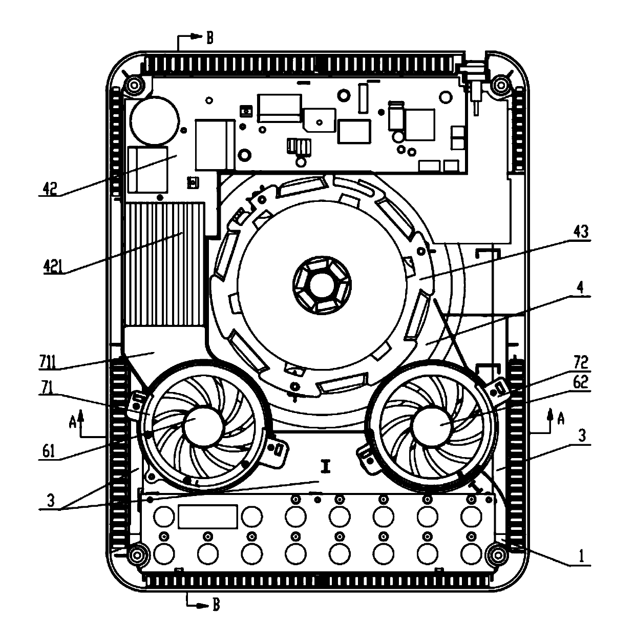
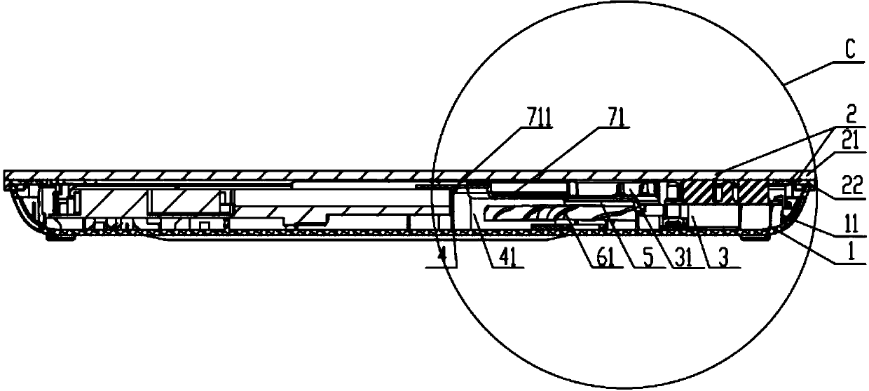
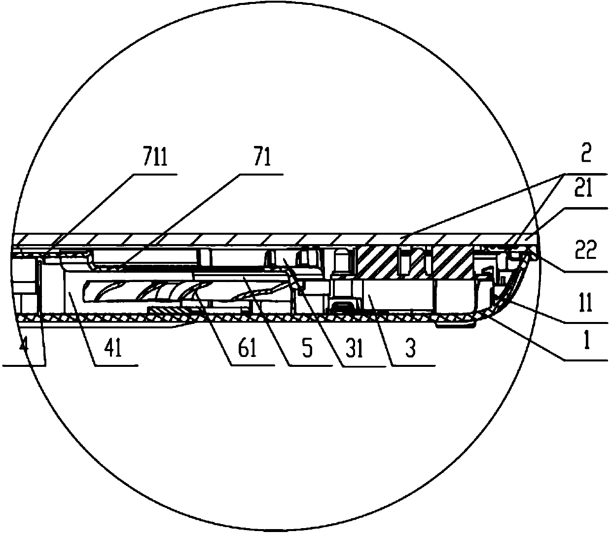
[0042] An induction cooker provided by the present invention comprises a base and an upper cover assembly, the base and the upper cover assembly form a furnace chamber, a fan is arranged in the furnace chamber, a fan cover is arranged on the periphery of the fan, a windshield rib is arranged on the base, the fan cover and The two sides of the windshield ribs respectively form a cold air chamber and a heating chamber; the side wall of the cold air chamber is provided with a side air inlet for the cooling air to enter the cold air chamber, and the side wall of the heating chamber is provided with a side outlet for the cooling air to exit the heating chamber tuyere.

[0043] The cooling air first enters the cold air chamber from the outside of the induction cooker through the side air inlet on the side...


PUM


Abstract

The invention discloses an electromagnetic oven, relates to the technical field of kitchen cooking, and is designed for solving the problems that the service life of electric elements is influenced as the moisture on the surface of a cooking table is easily sucked, and the heat dissipation effect is poor in a conventional electromagnetic oven. The electromagnetic oven comprises a base and an upper cover assembly which form a furnace chamber, wherein a fan is arranged in the furnace chamber; a fan cover is arranged at the periphery of the fan; an air baffle rib is arranged on the base; a cold air cavity and a heating cavity are formed in the two sides of the fan cover and the air baffle rib respectively; a side air inlet through which cooling air enters the cold air cavity is formed in the side wall of the cold air cavity, and a side air outlet through which the cooling air is discharged from the heating cavity is formed in the side wall of the heating cavity. According to the electromagnetic oven, the cooling air enters the side wall of the cold air cavity, so that the moisture on the surface of the cooking table is hardly sucked, the damage on the electric elements in the electromagnetic oven is avoided, and the service life of the electric elements is prolonged.

Description

technical field [0001] The invention relates to the technical field of kitchen cooking, in particular to an electromagnetic cooker. Background technique [0002] The induction cooker mainly uses the alternating magnetic field generated by the electromagnetic coil for heating. In order to generate the alternating magnetic field, it is necessary to pass high-frequency alternating current into the electromagnetic coil, so switching elements such as IGBT are required to control the current flowing into the electromagnetic coil. . This will cause excessive heat generation of electrical components such as IGBTs and electromagnetic coils, which requires a corresponding heat dissipation structure to be designed on the induction cooker. [0003] At present, the heat dissipation structure of the mainstream induction cooker on the market is as follows: install a fan on the base of the induction cooker, and set air inlets on the bottom wall and side wall of the base. The main air inlet...

Claims


Application Information

Patent Timeline
Patent Type & Authority Applications(China)
IPC IPC(8): F24C7/00F24C15/00F24C15/36
Inventor 潘海元谢武彬劳承云
Owner GREE ELECTRIC APPLIANCES INC
Why Eureka
Try Eureka