A stationary table for die cut

A technology of fixing table and fixing tube, applied in the direction of work table, manufacturing tools, etc., can solve the problems of increasing production cost, waste of resources, increasing mold processing time, etc., so as to improve the utilization rate and ensure the effect of cleanliness.

Inactive Publication Date: 2018-11-27
FOSHAN KUIFENG BUSINESS CONSULTATION SERVICES CO LTD
View PDF0 Cites 2 Cited by
  • Summary
  • Abstract
  • Description
  • Claims
  • Application Information

AI Technical Summary

Problems solved by technology

[0005] 1. The structure of the existing fixed table for die-cutting is relatively simple, and it directly fixes the mold with a specific shape. Because the mold specifications produced by the factory are different, the size of the mold is not uniform, so it is necessary to fix the mold with different specifications of the fixed table, so that The factory is required to have various types of fixed tables, resulting in waste of resources and increased production costs
[0006] 2. After cutting the mold with the fixed table for existing die-cutting, the debris generated by cutting the mold will also exist on the fixed table, and then a large amount of debris will adhere to the surface of the mold, and the surface of the mold needs to be cleaned again, thereby increasing Reduced mold processing time and reduced work efficiency

Method used


Image

  • A stationary table for die cut
  • A stationary table for die cut
  • A stationary table for die cut

Examples


Embodiment Construction

[0026] The following will clearly and completely describe the technical solutions in the embodiments of the present invention with reference to the accompanying drawings in the embodiments of the present invention. Obviously, the described embodiments are only some, not all, embodiments of the present invention. Based on the embodiments of the present invention, all other embodiments obtained by persons of ordinary skill in the art without making creative efforts belong to the protection scope of the present invention.

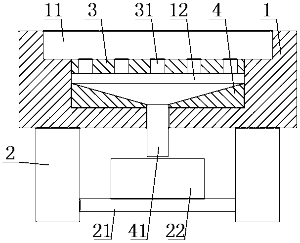
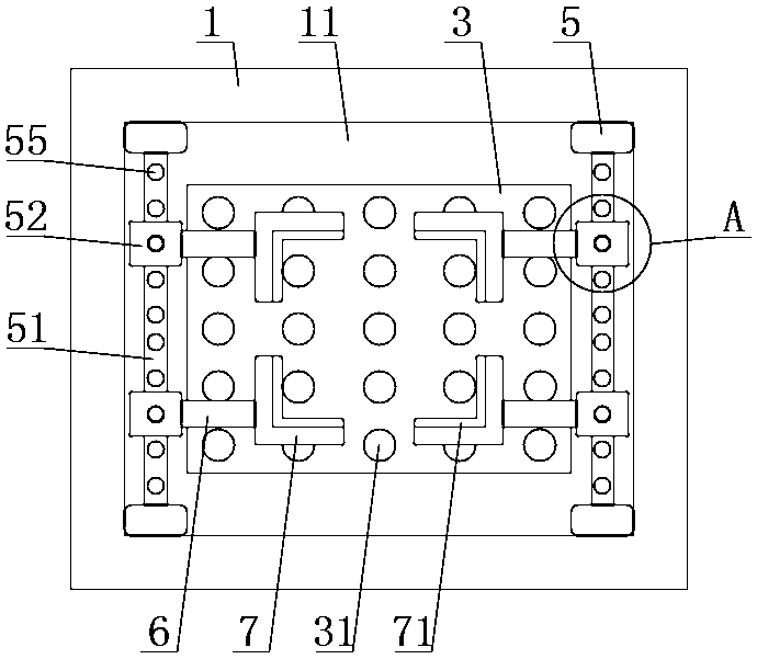
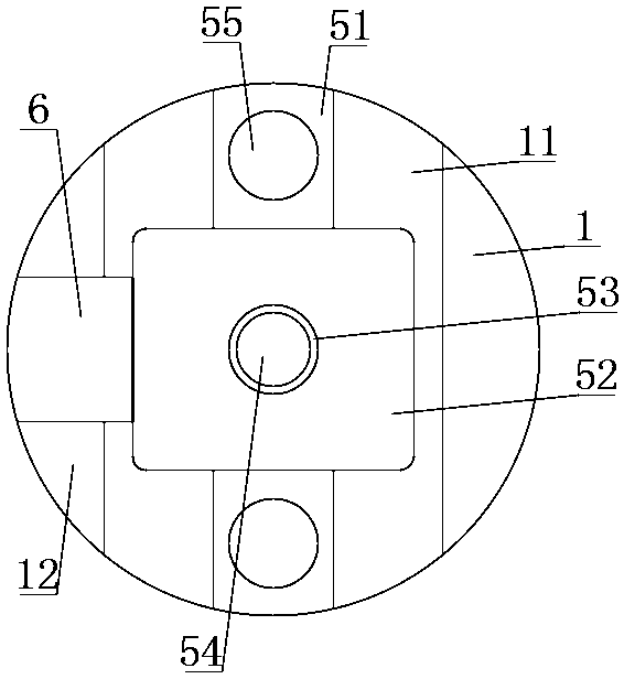
[0027] see Figure 1-4 , the present invention provides a technical solution: a fixed table for die-cutting, including a workbench 1, support legs 2, isolation plate 3, support plate 5, telescopic rod 6 and L-shaped splint 7, the lower surface of the workbench 1 Four support legs 2 are fixedly installed on the edge of the workbench 1 by bolts, a fixing groove 11 is provided at the center of the upper surface of the workbench 1, and a collection groove 12 is pr...


PUM


Abstract

A stationary table for die cut including workbench, support leg, support plate, telescopic bar and L-shaped splint, At that edge of the low surface of the workbench, four support legs are fixedly mount by bolts, A fixing groove is arranged at the center of the upper surface of the workbench, A collection groove is arranged at the bottom of the inner wall of the fixing groove, A through hole of waste material is uniformly arrange on that surface of the separating plate, the four corners of the inner side of the fixing groove are respectively fixedly installed with supporting plates through bolts, a sliding rod is fixedly installed at the center of the inner side of the support plate through bolts, A sliding sleeve is symmetrically slidably connecte with that outer wall of the sliding bar, As that slide sleeve slides on the out wall of the sliding rod, the sliding sleeve drives the L-shaped splint to move through the telescopic rod, and then the four L-shaped splint together fix the mold, the position of the L-shaped splint can be arbitrarily adjusted according to the size of the mold, and the L-shaped splint can fix the mold with different specifications.

Description

technical field [0001] The invention relates to the technical field of die cutting, in particular to a fixed table for die cutting. Background technique [0002] Molds, various molds and tools used in industrial production for injection molding, blow molding, extrusion, die-casting or forging forming, smelting, stamping, etc. to obtain the required products, in short, molds are tools used to make shaped objects , this tool is composed of various parts, and different molds are composed of different parts. It mainly realizes the processing of the shape of the article through the change of the physical state of the formed material. [0003] After the mold is formed, there will be excess trim on the outside of the mold, which needs to be cut off for the beauty of the mold. Currently cutting the trim of the mold is directly polished by a cutting knife. [0004] However, there are some disadvantages in the traditional use process, such as: [0005] 1. The structure of the existi...

Claims


Application Information

Patent Timeline
Patent Type & Authority Applications(China)
IPC IPC(8): B25H1/00
CPCB25H1/00
Inventor 不公告发明人
Owner FOSHAN KUIFENG BUSINESS CONSULTATION SERVICES CO LTD
Why Eureka
Try Eureka