Displacement assembly and variable valve lift device

A technology of valve lift and components, which is applied in the direction of valve devices, engine components, machines/engines, etc., can solve the problems of poor stability of switching valve lift, reduce the probability of interference, and reduce the process of switching valve lift. impact effect

Inactive Publication Date: 2018-11-27
ZHEJIANG GEELY HLDG GRP CO LTD +2
View PDF5 Cites 6 Cited by
  • Summary
  • Abstract
  • Description
  • Claims
  • Application Information

AI Technical Summary

Problems solved by technology

[0005] The purpose of the present invention is to provide a shifting assembly to solve the technical problem of poor stability of switching valve lift in the prior art

Method used


Image

  • Displacement assembly and variable valve lift device
  • Displacement assembly and variable valve lift device
  • Displacement assembly and variable valve lift device

Examples


Embodiment 1

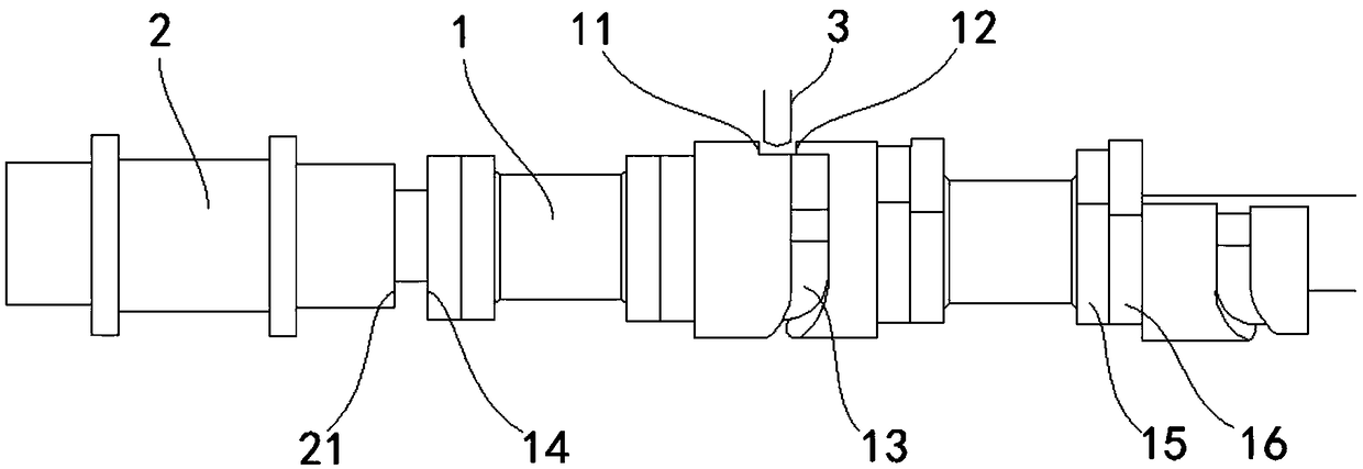
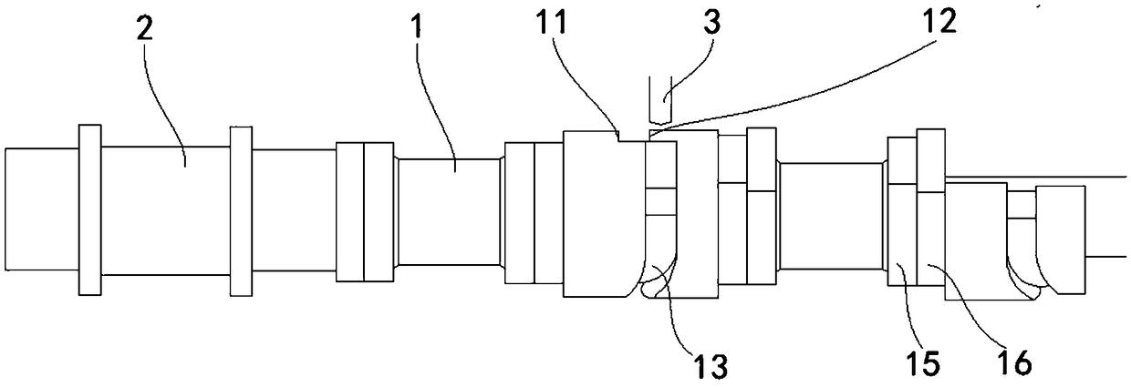
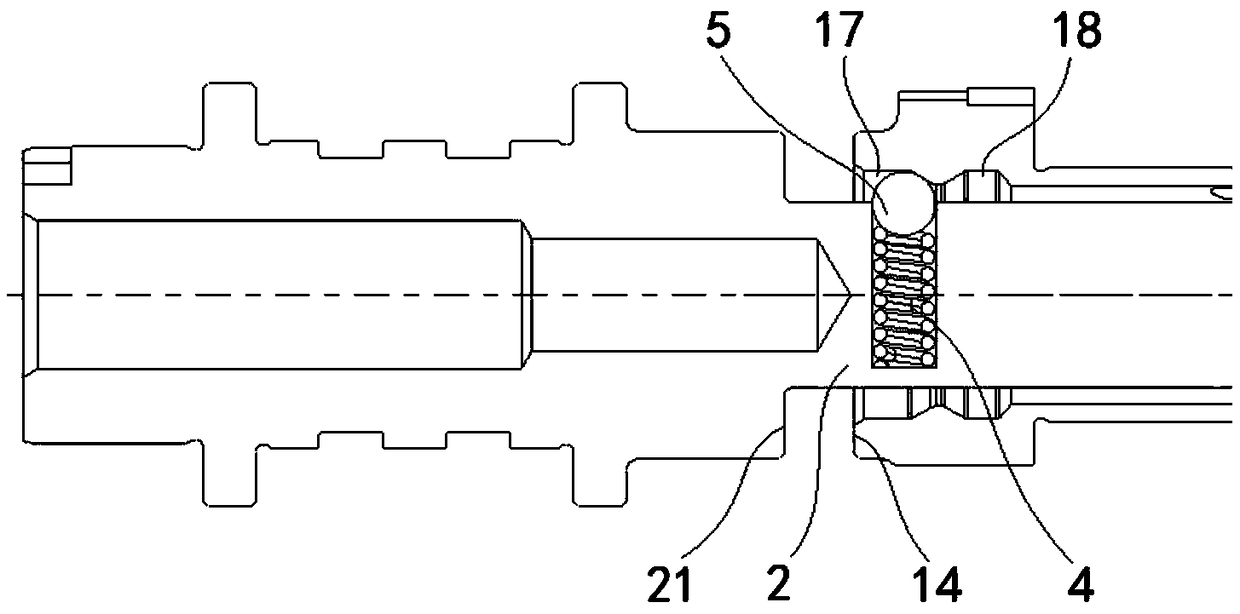
[0041] The displacement assembly provided by this embodiment, such as Figure 1 to Figure 4 As shown, including the shift sleeve 1; the outer wall of the shift sleeve 1 is provided with a groove, the groove is arranged in a spiral shape around the axis of the shift sleeve 1, and the distance between the two side walls at each end of the groove Both are greater than the distance between the two side walls in the middle of the groove.

[0042] When in use, the shift sleeve 1 is arranged on the mandrel 2, which can drive the shift sleeve 1 to rotate around the axis of the mandrel 2 when the mandrel 2 rotates. At this time, the pin shaft 3 is inserted into the groove to drive the shift The sleeve 1 moves along the axial direction of the mandrel 2, thereby driving the cam on the mandrel 2 to move to a suitable position along the axial direction of the mandrel 2, so as to adjust the valve lift. Because the width of the groove is variable, the width of the two ends of the groove is ...

Embodiment 2

[0062] The variable valve lift device provided by this embodiment, such as Figure 1 to Figure 4 As shown, it includes the mandrel 2, the executive assembly and the shifting assembly described in Embodiment 1; the shifting sleeve 1 is sleeved on the mandrel 2, and the mandrel 2 can drive the shifting sleeve 1 to rotate around the axis of the mandrel 2; The actuator assembly includes a pin shaft 3 that can extend into and out of the groove. When the pin shaft 3 extends into the groove, the pin shaft 3 can slide along the groove to drive the shift sleeve 1 to slide axially along the mandrel 2 .

[0063] When in use, the shift sleeve 1 is arranged on the mandrel 2, which can drive the shift sleeve 1 to rotate around the axis of the mandrel 2 when the mandrel 2 rotates. At this time, the pin shaft 3 is inserted into the groove to drive the shift The sleeve 1 moves along the axial direction of the mandrel 2, thereby driving the cam on the mandrel 2 to move to a suitable position al...


PUM


Abstract

The invention provides a displacement assembly and a variable valve lift device, and relates to the technical field of vehicles. The displacement assembly comprises a displacement sleeve; a groove isformed in the outer wall of the displacement sleeve, and is spirally arranged in the axis of the displacement sleeve, and the distance between the two side walls of each end of the groove is larger than the distance between the two side walls of the middle of the groove. When the displacement assembly is used, the displacement sleeve is arranged on a core shaft, the core shaft rotates to be capable of driving the displacement sleeve to rotate in the axis of the core shaft, a pin shaft extends into the groove at this moment so that the displacement sleeve can be driven to move in the axial direction of the core shaft, and therefore a cam on the core shaft is driven to move to the suitable position in the axial direction of the core shaft to adjust valve lift. As the width of the groove is variable, the widths of the two ends of the groove are larger that the width of the middle of the groove, and when the pin shaft extends into and extends out of the two ends of the groove, the probability when interference occurs between the pin shaft and the side wall of the groove can be reduced, impact of the pin shaft to the displacement sleeve is reduced, and the process of adjusting the valvelift is more stable.

Description

technical field [0001] The invention relates to the technical field of automobiles, in particular to a displacement assembly and a variable valve lift device with the displacement assembly. Background technique [0002] With the development of the automobile industry, automobile users have continuously increased requirements on fuel consumption and performance. The requirements for fuel economy and power performance indicators are also getting higher and higher. The variable valve lift technology is applied to the engine. At low speed, the torque is sufficient and the small valve lift is used to increase the turbulence in the cylinder to increase the combustion speed. At high speed, the horsepower is strong and the large valve lift is used to increase the intake air volume. , to increase power output at high speeds. It can effectively improve the fuel consumption and carbon dioxide emission of the internal combustion engine, reduce the emission of engine pollutants, and at...

Claims


Application Information

Patent Timeline
Patent Type & Authority Applications(China)
IPC IPC(8): F01L13/00
CPCF01L13/0036F01L2013/0052
Inventor 陈涛刘胜强廖乾畅赵波郭强姚君韦周武明刘东赵福成王瑞平
Owner ZHEJIANG GEELY HLDG GRP CO LTD
Why Eureka
Try Eureka