Jack connector assembly
A technology of connectors and contacts, which is applied in the manufacture of contacts, components of connecting devices, connections, etc., can solve the problems of high cost and achieve the effects of strong elastic stability, enhanced reliability, and reliable electrical contact
- Summary
- Abstract
- Description
- Claims
- Application Information
AI Technical Summary
Problems solved by technology
Method used
Image

Examples
no. 1 approach
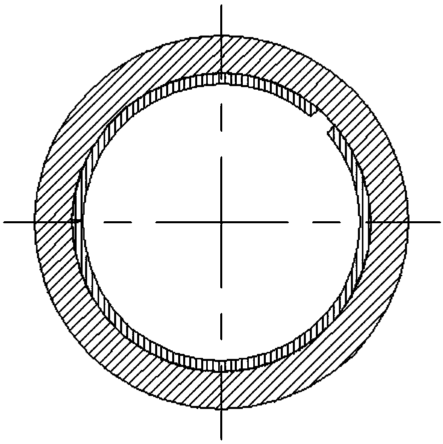
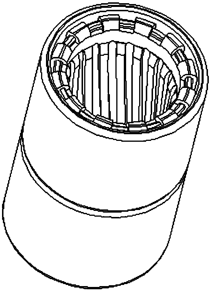
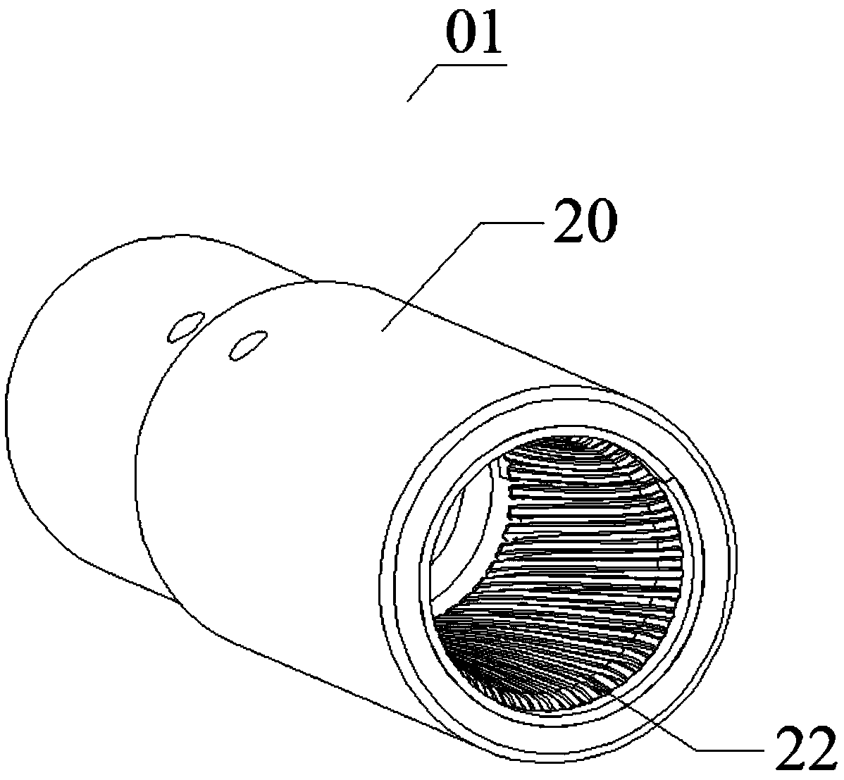
[0059] Figure 2a A perspective view of the jack connector according to the first embodiment of the present application is shown. Figure 2b A sectional view along the axis of the receptacle connector according to the first embodiment of the present application is shown. Figure 2c An exploded view of the jack connector according to the first embodiment of the present application is shown. Figure 2d It shows a perspective view of the contact piece before the port is tightly closed according to the first embodiment of the present application. Figure 2e It shows a perspective view of the contact piece merger port according to the first embodiment of the present application after it is tightly closed. Figure 2f A schematic diagram showing a thin-walled cylindrical structure in which the contact member according to the first embodiment of the present application is formed.
[0060] Such as Figure 2a , 2b As shown in and 2c, the receptacle connector 01 according to the fir...
no. 2 approach
[0072] Figure 3a An exploded view of the jack connector according to the second embodiment of the present application is shown. Figure 3b A sectional view along the axis of the receptacle connector according to the second embodiment of the present application is shown.
[0073] Such as Figure 3a , Figure 3b As shown, the second embodiment of the present application is an improvement on the first embodiment, and only the differences are described here, and the same components still use the same reference numerals. The difference between the jack connector 02 involved in the second embodiment of the present application and the jack connector 01 involved in the first embodiment is that the jack connector 02 includes a jack sleeve 201, and the jack sleeve 201 includes The cylindrical contact sleeve 201a and the outer sleeve 201b. First install the cage-type cylindrical contact piece 22 in the inner hole of the outer sleeve 201b to form a universal piece, and then install t...
no. 3 approach
[0075] Figure 4a An exploded view of the jack connector according to the third embodiment of the present application is shown. Figure 4b A sectional view along the axis of the receptacle connector according to the third embodiment of the present application is shown.
[0076] Such as Figure 4a , Figure 4b As shown, the third embodiment of the present application is an improvement on the first embodiment, and only the differences are described here, and the same components still use the same reference numerals. The difference between the jack connector 03 involved in the third embodiment of the present application and the jack connector 01 involved in the first embodiment is that the jack connector 03 includes a jack sleeve 202, and the jack sleeve 202 includes A cylindrical contact sleeve 202a. The cylindrical contact sleeve 202a has a riveted compression opening 202b at the port where the contact pin is inserted. The riveting compression opening 202b has a smaller dia...
PUM
 Abstract
Description
Claims
Application Information
 - R&D
- Intellectual Property
- Life Sciences
- Materials
- Tech Scout
- Unparalleled Data Quality
- Higher Quality Content
- 60% Fewer Hallucinations
Browse by: Latest US Patents, China's latest patents, Technical Efficacy Thesaurus, Application Domain, Technology Topic, Popular Technical Reports.
© 2025 PatSnap. All rights reserved.Legal|Privacy policy|Modern Slavery Act Transparency Statement|Sitemap|About US| Contact US: help@patsnap.com