Fiber optic connectors and their tail wiring assemblies

A technology for optical fiber connectors and wiring components, applied in optical components, instruments, optics, etc., can solve the problems of low reliability and pass rate, scratches and damage, avoid low reliability and pass rate, ensure safety, The effect of simplifying the overall structure

Active Publication Date: 2022-01-25
CHINA AVIATION OPTICAL-ELECTRICAL TECH CO LTD
View PDF7 Cites 0 Cited by
  • Summary
  • Abstract
  • Description
  • Claims
  • Application Information

AI Technical Summary

Problems solved by technology

[0005] The purpose of the present invention is to provide a tail wiring assembly for optical fiber connectors, which can solve the problem that the optical fiber is easily scratched and damaged by the inner wall of the existing optical fiber connector during assembly, and the debris generated by the scratches affects the optical signal transmission. The problem of low reliability and pass rate caused by

Method used


Image

  • Fiber optic connectors and their tail wiring assemblies
  • Fiber optic connectors and their tail wiring assemblies
  • Fiber optic connectors and their tail wiring assemblies

Examples


Embodiment 1

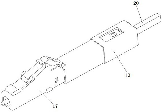
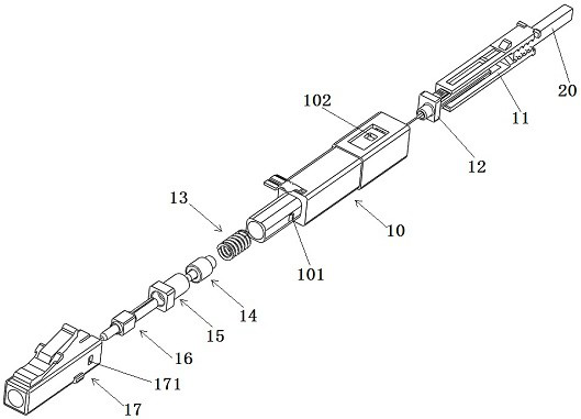
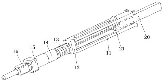
[0092] Embodiment 1 of the optical fiber connector in the present invention: the optical fiber connector in this embodiment is used to connect LC-type optical fibers, and can meet the requirement of fast on-site wiring of LC-type optical fibers. like figure 1 and figure 2 As shown, the optical fiber connector mainly includes a front housing 17, a ferrule assembly and a tail wiring assembly, and the tail wiring assembly includes a main housing 10, a fiber protection sliding sleeve 12 and an optical cable fixing member 11, which constitute the components of the optical fiber connector. There are many, so the structure of each part of the fiber optic connector is now explained.

[0093] The main housing 10 in the tail wiring assembly is installed on the rear end of the front housing 17 when assembling the optical fiber connector, and is assembled with the front housing 17 to form a shell, and the two sides of the main housing 10 are provided with triangular main housings buckl...

Embodiment 2

[0112]Embodiment 2 of the optical fiber connector in the present invention: the difference from the above-mentioned embodiments is that in this embodiment, the fiber protection sliding sleeve is inserted into the optical cable fixing member, and the wall surface in the optical cable fixing member that cooperates with the fiber protection sliding sleeve A rubber strip or a frosted surface is arranged on the upper part, and the friction force between the fiber protection sliding sleeve and the rubber strip or the frosted surface is large, which can realize the sliding resistance cooperation between the fiber protection sliding sleeve and the optical cable fixing member in the direction of the insertion sleeve. When the fiber protection sliding sleeve is extended, the operator needs to exert force to overcome the friction between the fiber protection sliding sleeve and the optical cable fixing member, so that the fiber protection sliding sleeve can be extended or retracted into the...

Embodiment 3

[0113] Embodiment 3 of the optical fiber connector in the present invention: The difference from the above-mentioned embodiments is that the size of the largest outline of the fiber protective sliding sleeve in this embodiment is larger than that of the optical cable fixing member, and the optical cable fixing member is inserted and sleeved on the fiber protection. in sliding sleeve. A slider is arranged on the outer surface of the optical cable fixing piece, and a guide groove is arranged on the inner wall surface of the fiber protection sliding sleeve. In other embodiments, the cross sections of the fiber protection sliding sleeve and the optical cable fixing member are both rectangular or circular, and the fiber protection sliding sleeve and the optical cable fixing member are guided and matched by the inner and outer surfaces of the fiber protection sliding sleeve and the optical cable fixing member.

[0114] Embodiment 4 of the optical fiber connector in the present inven...


PUM


Abstract

The present invention provides an optical fiber connector and its tail wiring assembly, which can solve the problem of the optical fiber being easily scratched and damaged by the inner wall of the existing optical fiber connector during assembly, and the debris generated by the scratching affecting the transmission of optical signals. Sexuality and low pass rate. The tail wiring assembly includes the main housing and the cable fixing piece; the fiber protection sliding sleeve is fitted with the fiber optic cable fixing piece; the fiber protection sliding sleeve has an extension position and a retraction position relative to the fiber optic cable fixing piece; The fixing parts together form a fiber protection space; when in the retracted position, the optical fiber can protrude from the front end of the fiber protection sliding sleeve; When they are not subjected to external force, they remain relatively fixed; the inner cavity of the main housing is provided with a blocking structure, which can be matched with the front end of the fiber protection sliding sleeve to make the fiber protection sliding sleeve overcome the sliding resistance force of the cable fixing piece. Retraction; the main housing is also provided with an opening for the optical fiber to protrude from the main housing.

Description

technical field [0001] The invention relates to an optical fiber connector and a tail wiring assembly thereof. Background technique [0002] The scheme of using optical fiber to transmit optical signals is widely used and mature, and because the positions of the two modules connected by optical fiber are uncertain, technicians arrange the optical fiber on site according to the distance between the two modules, and then connect the optical fiber connector with the The optical fiber is assembled and connected, and finally the optical fiber connector is inserted into the module. Existing optical fiber connectors are formed by nesting and combining multiple parts. For example, an optical cable connector disclosed in a patent document with the authorized announcement number CN207851354U and the authorized announcement date of 2018.09.11 includes a single butt joint housing. The front cover and the simplex back cover, and the ferrule assembly installed in the housing, the ferrule...

Claims


Application Information

Patent Timeline
Patent Type & Authority Patents(China)
IPC IPC(8): G02B6/38
CPCG02B6/3855G02B6/3849G02B6/389G02B6/3887
Inventor 杨尚矗
Owner CHINA AVIATION OPTICAL-ELECTRICAL TECH CO LTD
Why Eureka
Try Eureka