Electrified ice melting topological system and ice melting method thereof

An ice-melting method and ice-melting technology, applied in the installation of electrical components, cables, overhead installation, etc., can solve the problems of high line structure requirements, inability to be well promoted and used, and high system consumption, so as to improve the ice resistance level Effect

Active Publication Date: 2018-11-27
STATE GRID HUNAN ELECTRIC POWER +2
View PDF8 Cites 5 Cited by
  • Summary
  • Abstract
  • Description
  • Claims
  • Application Information

AI Technical Summary

Problems solved by technology

Among them, the live ice-melting topology system based on the unified power flow controller consumes a lot of energy and easily leads to system instability; the live-line ice-melting topology structure based on double-circuit lines between substations has high requirements on the line structure and narrow application range; based on load current transfer The charged ice-melting topology can only be applied to 4-split and above conductors, and the ice-melting efficiency is low
The current topological structure of electrified ice melting cannot be well promoted and used, and cannot solve the adverse consequences caused by the power outage and ice melting of the existing system

Method used


Image

  • Electrified ice melting topological system and ice melting method thereof
  • Electrified ice melting topological system and ice melting method thereof

Examples


Embodiment 1

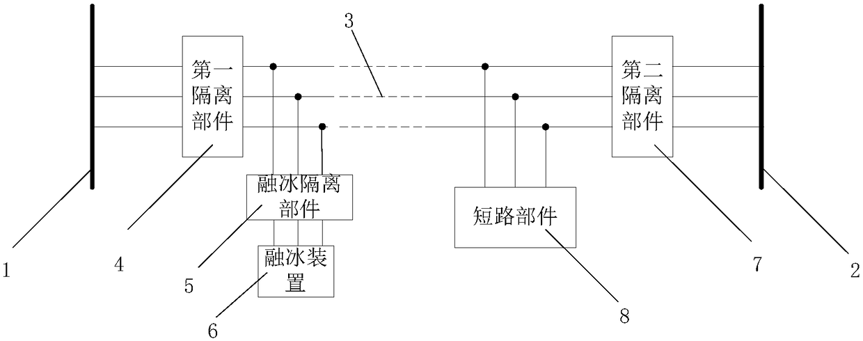
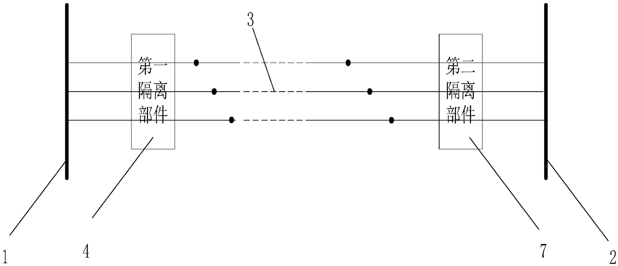
[0022] like figure 1 As shown, this embodiment provides a live ice-melting topological system, including an ice-melting isolation part 5 arranged in parallel on the power transmission line 3, an ice-melting device 6 connected in series outside the ice-melting isolation part 5, and connected in parallel to the power transmission line 3. The short-circuit component 8 on the line 3 is used for short-circuiting the ice-melting current on the transmission line 3 .

[0023] In practical applications, the short-circuit component 8 can be designed as a band-resistance wave blocking circuit, which can be cut off at 50 Hz and turned on at other frequencies. Specifically, the short-circuit component 8 is used to short-circuit the A, B, and C three-phase lines of the transmission line 3, and is in a short-circuit state when it is turned on. After short-circuiting, any phase line in the A, B, and C three-phase lines can be To melt ice, at this time, the short-circuit component 8 is in an ...

Embodiment 2

[0031] This embodiment provides an ice-melting method applied to the charged ice-melting topological system in the above-mentioned embodiment 1, including the following steps:

[0032] S1: Connect the ice-melting isolation part 5 to the power transmission line 3 in parallel, and connect the ice-melting device 6 in series to the outside of the ice-melting isolation part 5, and connect the short-circuit part for short-circuiting the power transmission line 3 in series on the power transmission line 3 8;

[0033] S2: Detect the icing situation on the transmission line 3, when the icing value on the transmission line 3 is greater than or equal to the icing warning value, turn on the ice-melting isolation part 5 and the short-circuit part 8, and the ice-melting device 6 generates ice-melting voltage and form ice-melting channels.

[0034] In this embodiment, steps are also included:

[0035] S3: When the ice coating value on the power transmission line 3 is less than the ice coat...


PUM


Abstract

The invention relates to the technical field of electrical engineering and discloses an electrified ice melting topological system and an ice melting method thereof. Ice melting a plurality of lines is realized under the condition that normal power supply of a power transmission line is not influenced, so that an anti-ice level of a power grid is improved; the ice melting topological system disclosed by the invention comprises an ice melting isolation part which is arranged on the power transmission line in parallel, an ice melting device which is connected to the outer side of the ice meltingisolation part in series, and a short-circuit part which is connected onto the power transmission line in parallel and is connected with the ice melting isolation part in series, and is in short connection with the power transmission line.

Description

technical field [0001] The invention relates to the technical field of electrical engineering, in particular to an electrified ice-melting topological system and an ice-melting method thereof. Background technique [0002] In recent years, rain, snow and freezing disasters have occurred frequently in the southern region, which has seriously affected the operation of the power grid. Current ice melting is currently the most direct and effective measure to deal with power grid ice disasters. However, the existing ice melting methods are mainly based on power outages. On the one hand, a large number of users will be cut off after a power outage, which will affect the quality service of the power supply company and affect people’s daily life; on the other hand, when multiple lines When the line needs to melt ice, in order to ensure the safety of power supply, the power cannot be cut off at the same time to melt the ice, and it must be carried out sequentially, so that the ice is...

Claims


Application Information

Patent Timeline
Patent Type & Authority Applications(China)
IPC IPC(8): H02G7/16
CPCH02G7/16
Inventor 陆佳政朱远李波谭艳军朱思国黄清军毛新果
Owner STATE GRID HUNAN ELECTRIC POWER
Why Eureka
Try Eureka