
Tin soldering placing device for filter pin

A filter and tin passing technology, which is applied in the field of placement devices for tin passing through filter pins, can solve the problem that the placement device for passing tin passing through filter pins does not have a fixed function, etc., and achieves convenient rotation, avoids falling off, and reinforces stability. Effect

Inactive Publication Date: 2018-11-30
LEIYANG YAXIANG ELECTRONICS TECH
View PDF0 Cites 0 Cited by
  • Summary
  • Abstract
  • Description
  • Claims
  • Application Information

AI Technical Summary

Problems solved by technology

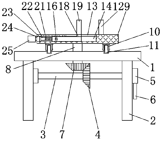
[0003] The purpose of the present invention is to provide a placement device for filter pin passing tin, which has the advantage of fixing function, and solves the problem that the existing filter pin passing tin placing device does not have the fixing function

Method used

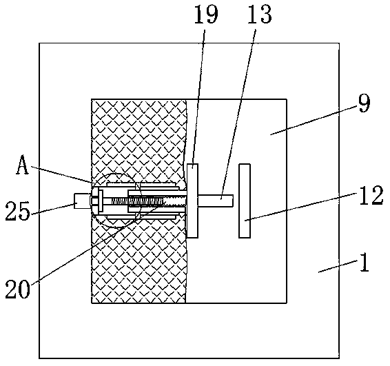
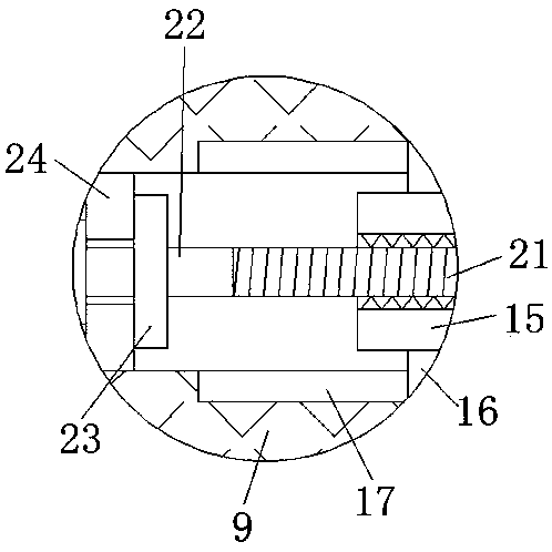

Image

  • Tin soldering placing device for filter pin
  • Tin soldering placing device for filter pin
  • Tin soldering placing device for filter pin

Examples


Embodiment Construction

[0016] The following will clearly and completely describe the technical solutions in the embodiments of the present invention with reference to the accompanying drawings in the embodiments of the present invention. Obviously, the described embodiments are only some, not all, embodiments of the present invention. Based on the embodiments of the present invention, all other embodiments obtained by persons of ordinary skill in the art without making creative efforts belong to the protection scope of the present invention.

[0017] see Figure 1-3 , a device for placing filter pins through tin, including a base 1, a support plate 2 is fixedly connected to both sides of the bottom of the base 1, and a first rotating rod 3 is movably connected to the opposite sides of the two support plates 2 The right side of the surface of the first rotating rod 3 is covered with a first bevel gear 4, the right side of the first rotating rod 3 penetrates to the right side of the support plate 2 an...


PUM


Abstract

The invention discloses a tin soldering placing device for a filter pin. The device comprises a base. Supporting plates are fixedly connected to two sides of the bottom of the base, a first rotary rodis movably connected between the sides, opposite to each other, of the two supporting plates, a first bevel gear is arranged on the right side of the surface of the first rotary rod in a sleeving mode, and the right side of the first rotary rod penetrates the right sides of the supporting plates and is fixedly connected to a rotary disc. By arranging the base, the supporting plates, the first rotary rod, the first bevel gear, the rotary disc, a handle, a second bevel gear, a second rotary rod, a placing plate, a bracket, rollers, a fixed plate, an opening, a groove, a movable rod, a slide bar, a first chute, a connecting plate, a movable plate, a threaded groove, a threaded rod, a third rotary rod, a limiting plate, a fixed block and a rotary knob matched in use, the problem that an existing tin soldering placing device for the filter pin does not have a fixing function is solved. The tin soldering placing device for the filter pin has the advantage of having the fixing function.

Description

technical field [0001] The invention relates to the technical field of filter processing, in particular to a placement device for tinning of filter pins. Background technique [0002] The power filter is a filter circuit composed of capacitors, inductors and resistors. The filter can effectively filter out the frequency points of a specific frequency in the power line or frequencies other than this frequency point, obtain a power signal of a specific frequency, or eliminate a For the power signal after a specific frequency, in the process of soldering the filter pins, it is necessary to use a placement device to place the filter pins. The existing filter pin placement device does not have a fixed function. The filter The pins are easy to move, and the improper operation of the user will cause damage to the pins of the oscilloscope, which will bring losses to the user. Contents of the invention [0003] The object of the present invention is to provide a placement device f...

Claims


Application Information

Patent Timeline
IPC IPC(8): B23K3/08B23K101/36
CPCB23K3/087
Inventor 陈小勇龚亮朱千林
Owner LEIYANG YAXIANG ELECTRONICS TECH
Learn More