
Pendulum clock structure with convenience in adjusting swing angles and technology for processing pendulum clock structure

A technology of swing angle and pendulum clock, applied in the field of pendulum clock structure and its processing technology, can solve the problems such as the swing angle of the pendulum clock mechanism is not easy to be controlled, and the product cannot reach the laser processing position, etc., so as to control the defect rate and solve the laser processing quality. Problems, the effect of simple operation

Inactive Publication Date: 2018-11-30
SUZHOU RADIANT AUTOMATIC EQUIP TECH CO LTD
View PDF0 Cites 0 Cited by
  • Summary
  • Abstract
  • Description
  • Claims
  • Application Information

AI Technical Summary

Problems solved by technology

[0002] When processing laser products, it is necessary to place the product on the product carrier, and then adjust the angle of the laser to realize laser processing on different positions of the product. In the process of angle adjustment, it is also necessary to consider the relationship between the product to be processed and the laser processing equipment. The distance between them, while the existing pendulum clock mechanism usually uses the lug plate to directly connect with the mounting parts through bolts. The swing angle of the pendulum clock mechanism is not easy to be controlled, and the product cannot reach a fixed laser processing position.

Method used


Image

  • Pendulum clock structure with convenience in adjusting swing angles and technology for processing pendulum clock structure
  • Pendulum clock structure with convenience in adjusting swing angles and technology for processing pendulum clock structure

Examples


Embodiment Construction

[0025] The present invention will be further explained below in conjunction with the accompanying drawings and specific embodiments.

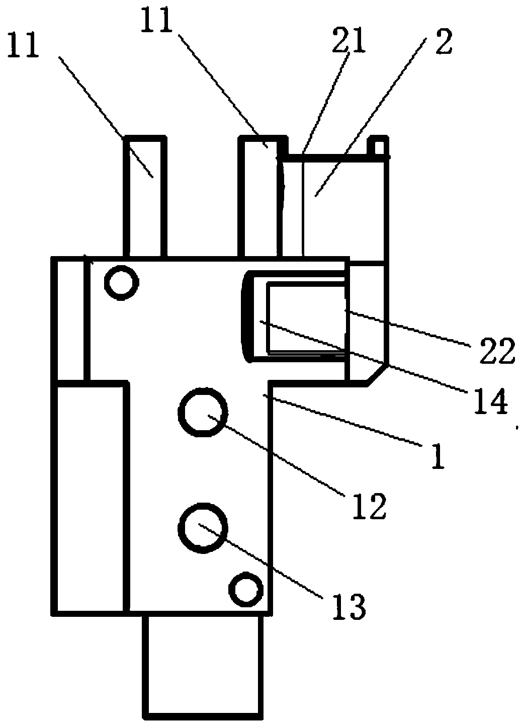
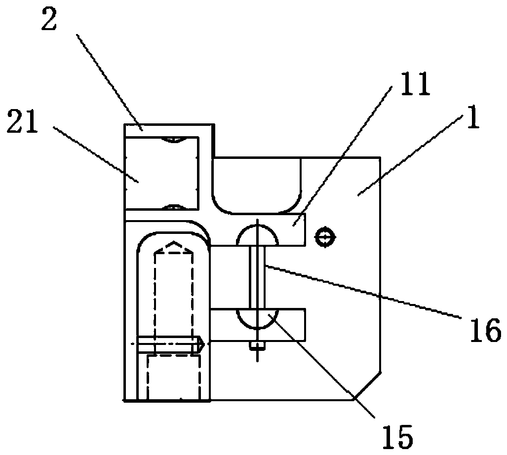
[0026] Such as Figure 1-2 A structure of a pendulum clock that is convenient for adjusting the swing angle is shown, including the pendulum clock itself

[0027] body 1 and auxiliary support 2, the pendulum clock body 1 is fixed on the auxiliary support 2, the auxiliary support 2 is provided with a mounting hole 3, and the top of the pendulum body 1 is provided with two ear plates 11, the ear plates 11 A mounting hole 3 is provided on the pendulum body 1, and a positioning hole 12 and a positioning hole 13 are set in the middle position of the pendulum body 1. The depth of the positioning hole 12 is greater than the depth of the positioning hole 2 13, and the middle section of the pendulum body 1 is in the shape of L type.

[0028] In this embodiment, the pendulum body 1 is fixed on the auxiliary support through the tooth holes.

[0029] In...


PUM


Abstract

The invention discloses a pendulum clock structure with convenience in adjusting swing angles. The pendulum clock structure comprises a pendulum clock body and an auxiliary support seat. The pendulumclock body is fixed onto the auxiliary support seat, a mounting hole is formed in the auxiliary support seat, two lug plates are arranged on the top of the pendulum clock body, mounting holes are formed in the lug plates, a first positioning hole and a second positioning hole are formed in the middle of the pendulum clock body, the first positioning hole is deeper than the second positioning hole,and the pendulum clock body is provided with an integrally L-shaped middle section. The pendulum clock structure has the advantages that the pendulum clock structure is reasonable in structural design; the auxiliary support seat is added to an original pendulum clock structure, mounting and positioning holes are formed in the auxiliary support seat, accordingly, the pendulum clock structure is simple and accurate and can be easily, quickly and conveniently operated, the laser processing quality problems can be effectively solved, and the defect rate can be controlled.

Description

technical field [0001] The invention relates to a pendulum structure, in particular to a pendulum structure which is convenient for adjusting the swing angle and its processing technology. Background technique [0002] When processing laser products, it is necessary to place the product on the product carrier, and then adjust the angle of the laser to realize laser processing on different positions of the product. In the process of angle adjustment, it is also necessary to consider the relationship between the product to be processed and the laser processing equipment. The distance between them, while the existing pendulum clock mechanism usually uses the lug plate to directly connect with the mounting parts through bolts. The swing angle of the pendulum clock mechanism is not easy to be controlled, and the product cannot reach a fixed laser processing position. [0003] Therefore, there is a need for a pendulum clock structure that is convenient for adjusting the swing angl...

Claims


Application Information

Patent Timeline
Patent Type & Authority Applications(China)
IPC IPC(8): B23P15/00G04B5/02
CPCB23P15/00G04B5/02
Inventor 肖英肖绪样罗刚周峰魏俊汪凯王海超徐克明
Owner SUZHOU RADIANT AUTOMATIC EQUIP TECH CO LTD
Learn More