Centrifuge

Active Publication Date: 2014-05-01
EPPENDORF HIMAC TECH CO LTD
View PDF12 Cites 7 Cited by
  • Summary
  • Abstract
  • Description
  • Claims
  • Application Information

AI Technical Summary

Benefits of technology

[0012]A centrifuge according to the present invention includes: a rotor chamber containing a rotor in which a sample is loaded; a motor rotary driving the rotor; a cooling unit cooling temperature of the rotor chamber; a temperature sensor detecting the temperature of the rotor chamber; an input unit inputting operation conditions of the rotor; and a control unit controlling the motor in a steady operation mode of rotating the rotor at a setting rotation speed and for a setting time inputted by the input unit and a deceleration stop mode of stopping the rotor by deceleration after the steady operation mode is finished. In the centrifuge, the control unit controls the cooling unit such that, when the setting rotation speed is higher or equal to a predetermined value, a target controlled temperature of the rotor chamber is set from a first target controlled temperature to a second target controlled temperature that is higher than the first target controlled temperature before starting deceleration of the rotor.
[0013]In the centrifuge according to the present invention, changes in the target controlled temperature made by the control unit is performed only when the set temperature inputted by the input unit is lower than or equal to a predetermined value. In the centrifuge according to the present invention, when the setting rotation speed becomes 40% or more of a maximum rotation speed, the first target controlled temperature is changed to the second target controlled temperature. In the centrifuge according to the present invention, the cooling unit includes a compressor which compresses a cooling medium flowed out from a cooling pipe in which the cooling medium is circulated, and controls the temperature of the rotor by changing a rotation speed of the compressor. In the centrifuge according to the present invention, the cooling unit includes a cooling pipe in which a cooling medium is circulated, and a circulating pipe sending back the cooling medium flowed out from an outlet port of the cooling pipe to an inlet port of the cooling pipe via the compressor, a bypass pipe bypassing the compressor is provided to the circulating pipe, and the temperature of the rotor chamber is controlled by adjusting a flow rate of the bypass pipe. In the centrifuge according to the present invention, a rotation axis of the motor has a rotor identifier for identifying a type of the rotor attached to the rotation axis, and when windage loss calculated from the type of the rotor and the rotation speed of the rotor is larger than or equal to allowable windage loss limit value to windage loss of a maximum rotation speed of the rotor, the temperature of the rotor chamber is set at the second target controlled temperature. In the centrifuge according to the present invention, when the rotor is driven at a revolution speed higher than or equal to a limit rotation speed, the temperature of the rotor chamber is set to the second target controlled temperature. In the centrifuge according to the present invention, based on the type of the rotor and t

Problems solved by technology

When a rotor is rotated in this manner in which air exists in the rotor chamber, heat of friction of air and the rotor generated during the rotation of the rotor may be bigger and it might rise the temperature of the sample.
The amount of heat generation, that is, windage loss of the rotor is increased as the rotation speed of the rotor is increased.
Ho

Method used


Image

  • Centrifuge
  • Centrifuge
  • Centrifuge

Examples


Embodiment Construction

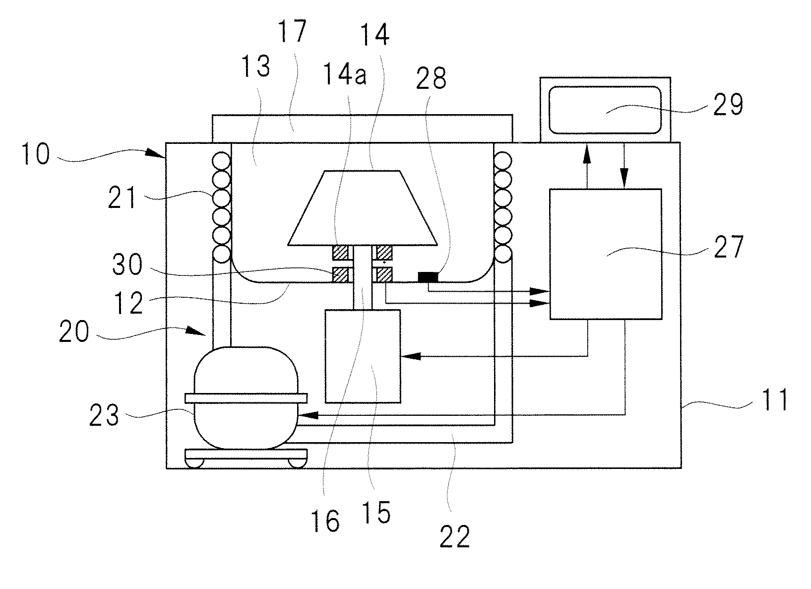
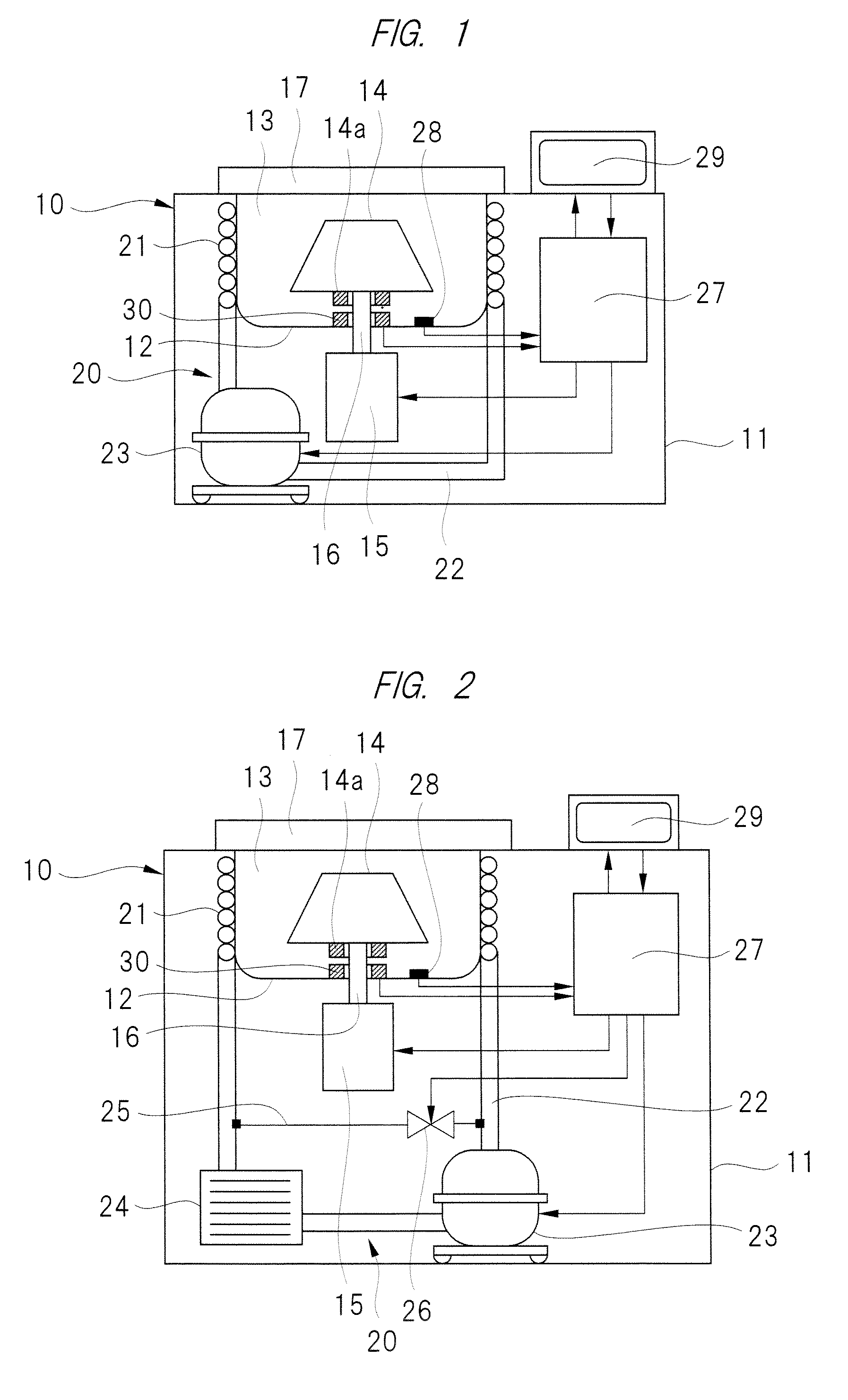
[0027]Hereinafter, embodiments of the present invention will be described in detail with reference to the accompanying drawings. A centrifugal separator, that is, a centrifuge 10 illustrated in FIG. 1 includes a frame 11 in a substantially cuboid shape formed of a box-form plate (sheet metal) or the like. Inside the frame 11, a bowl, that is, a storage container 12 formed of a metal thin plate is provided, and the inside of the container 12 is a rotor chamber 13. Inside the rotor chamber 13, a rotating body, that is, a rotor 14 is disposed. At a bottom portion of the storage container 12, a penetrating hole communicating the inside and outside of the rotor chamber 13 is provided, and a rotation axis 16 of an electric motor 15 as a driving unit penetrates the penetrating hole. The rotor 14 is detachably attached to a rotation axis 16 and driven to rotate by the electric motor 15. The electric motor 15 is controlled at an optional rotation speedup to, for example, 22,000 rpm maximum, ...


PUM


Abstract

Lowering of process quality of a sample is prevented even when a rotor is slowly decelerated taking a long time upon finishing a centrifugal process. A centrifuge having a steady operation mode of rotating a rotor at an inputted steady rotation speed and a deceleration stop mode of stopping the rotor by deceleration. When a remaining time of the steady operation mode is within a stop preparation time, a target controlled temperature of the rotor chamber is set from a first target controlled temperature to a second target controlled temperature that is higher than the first target controlled temperature. By setting the target controlled temperature of the rotor chamber high before switching to the deceleration stop mode, temperature of the rotor chamber is controlled to be close to a set temperature of the rotor and thus excessive cooling of a sample loaded to the rotor can be prevented.

Description

CROSS-REFERENCE TO RELATED APPLICATION[0001]The present application claims priority from Japanese Patent Application No. 2012-241245 filed on Oct. 31, 2012, the content of which is hereby incorporated by reference into this application.TECHNICAL FIELD OF THE INVENTION[0002]The present invention relates to a centrifuge, when takes liquids or a mixture of solids and liquids as sample, for a variety of centrifuging such as sedimentation isolation, purification, concentration to process the sample with centrifugal force.BACKGROUND OF THE INVENTION[0003]In the fields such as medical and pharmaceutical sciences and gene engineering, a centrifugal precipitator that is a centrifuge is used to process by, for example, sedimentation isolation in this taking a sample of liquids or a mixture of solids and liquids as a sample. A centrifuge has installed therein a rotor to which a container, such as tube or bottle, in which samples such as culture broth or blood is accommodated is loaded. The rot...

Claims


Application Information

Patent Timeline
IPC IPC(8): B04B9/10B04B15/02
CPCB04B9/10B04B15/02B04B13/00B04B13/003
Inventor HODOTSUKA, YUKI
Owner EPPENDORF HIMAC TECH CO LTD
Why Eureka
Try Eureka