Machining device for shaft sleeve oil groove

A processing device and oil tank technology, which is applied in the field of processing devices, can solve problems such as difficulty in meeting high-efficiency and large-volume production requirements, difficulty in ensuring the depth and width of oil tanks, and high requirements for workers' manipulation skills, so as to reduce repeated confirmation time and solve processing positions. Inaccurate, reduce the effect of processing cost and time

Inactive Publication Date: 2012-12-26
吴江同新自润滑轴承厂
View PDF0 Cites 7 Cited by
  • Summary
  • Abstract
  • Description
  • Claims
  • Application Information

AI Technical Summary

Problems solved by technology

Although this device is simple, it has the following disadvantages: 1. It is difficult to control the stroke of the tool, and it is difficult to ensure the depth and width of the oil groove during processing. Workers have high requirements for manipulating skills; 3. Long processing time and low production efficiency make it difficult to meet high-efficiency and large-volume production requirements

Method used


Image

  • Machining device for shaft sleeve oil groove

Examples


Embodiment Construction

[0013] Now, the present invention will be described in further detail in conjunction with the accompanying drawings and preferred embodiments.

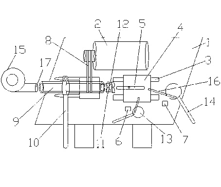
[0014] like figure 1 As shown, a shaft sleeve oil groove processing device includes a bed 1, a motor 2 arranged at the front end of the bed 1, a guide rail 3 is fixed on the bed 1, and a boss 4 is arranged on the guide rail 3. A tool 5 is fixed on the boss 4, and a first limiting plate 6 and a second limiting plate 7 are fixed on the left end of the bed 1 to determine the width and depth of the processing oil tank. The right end of the bed 1 is provided with There is a clamping part for clamping the bushing, wherein the clamping part includes a hollow main shaft 9, a ring rod 10 fixed to the main shaft 9 and four sector blocks 11, and the motor 2 is connected to the Clamp part connection.

[0015] The right side end surface of the main shaft 9 is obliquely fixed on the end surface of the sector block 11 by an iron bar 12, so as to r...


PUM


Abstract

The invention relates to a machining device for a shaft sleeve oil groove. The machining device for the shaft sleeve oil groove comprises a lathe body and a motor which is arranged on the front end of the lathe body, wherein a guide rail is fixed on the lathe body; a boss is arranged on the guide rail; a cutter is fixed on the boss; the left end of the lathe body is fixed with a first limiting plate and a second limiting plate; the right end of the lathe body is provided with a clamping component for clamping a shaft sleeve; and the motor is connected with the clamping part by a chain belt. The machining device for the shaft sleeve oil groove has the beneficial effect of being simple to operate and being precisely positioned to machine, thereby reducing repeated acknowledging time and solving inconvenience caused by an inaccurate oil groove machining position, greatly reducing machining cost and time, ensuring machining quality and improving production efficiency, and satisfying large-scale production requirements; and moreover, the machining device has the advantages of low cost, high quality and the like.

Description

technical field [0001] The invention relates to a processing device, in particular to a processing device for an oil groove of a shaft sleeve. Background technique [0002] In the moving parts, the wear of the parts is caused by long-term friction. When the shaft and the hole are worn to a certain extent, the parts must be replaced. Therefore, it is necessary to choose a shaft sleeve with lower hardness and better wear resistance, which can reduce shaft and hole wear. For the wear of the seat, in order to better match the movement of the sleeve and the shaft, it is necessary to open an oil groove on the inner surface of the sleeve to achieve the purpose of lubricating and storing lubricating oil, so as to prevent the shaft from being aggravated or even damaged due to lack of oil. The conventional processing device of the oil groove is formed by turning the inner surface of the workpiece with the screw rod to drive the forming tool. Although this device is simple, it has the...

Claims


Application Information

Patent Timeline
Patent Type & Authority Applications(China)
IPC IPC(8): B23D79/00
Inventor 王进
Owner 吴江同新自润滑轴承厂
Why Eureka
Try Eureka