Pedal assisting mechanism

An auxiliary mechanism and auxiliary motor technology, which is applied in the direction of braking action starting device, brake, transportation and packaging, etc., can solve the problems that the brake pedal device cannot be used for all vehicles, the development cost of the brake pedal is high, and the pedal feel is not easy to adjust. , to achieve the effects of shortening the development cycle, reducing development and manufacturing costs, and excellent pedal feel

Inactive Publication Date: 2018-11-30
GEELY AUTOMOBILE INST NINGBO CO LTD +1
View PDF4 Cites 2 Cited by
  • Summary
  • Abstract
  • Description
  • Claims
  • Application Information

AI Technical Summary

Problems solved by technology

[0003] However, the current pedal device has certain disadvantages. The pedal ratio is determined at the beginning of the design, and different vehicle models have different requirements for pedal force, pedal travel, and vehicle deceleration, so that the above-menti

Method used


Image

  • Pedal assisting mechanism
  • Pedal assisting mechanism

Examples


Embodiment Construction

[0017] In order to further explain the technical means and effects of the present invention to achieve the intended purpose of the invention, the specific implementation, structure, features and effects of the pedal assist mechanism of the present invention will be described in detail below with reference to the accompanying drawings and preferred embodiments. Rear.

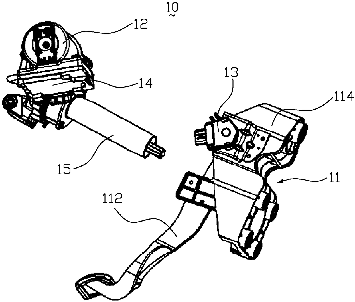
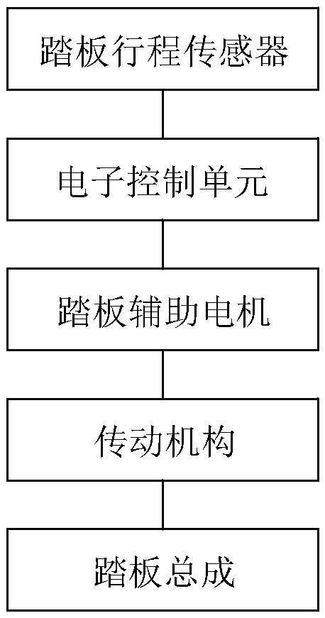
[0018] figure 1 It is a schematic diagram of the structure of the pedal assist mechanism of the present invention. figure 2 It is a schematic diagram of the control of the pedal assist mechanism of the present invention. Please refer to figure 1 with figure 2 , A pedal assist mechanism 10 includes a pedal assembly 11, a pedal assist motor 12, a pedal stroke sensor 13, an electronic control unit 14 and a transmission mechanism 15.

[0019] The pedal assembly 11 includes a brake pedal 112 and a bracket 114. The brake pedal 112 is installed on the bracket 114. The pedal stroke sensor 13 is provided on the bracket 114...


PUM


Abstract

The invention relates to a pedal assisting mechanism, which comprises a pedal assembly, a pedal assisting motor, a pedal travel sensor, an electronic control unit, and a transmission mechanism, the pedal assembly comprises a brake pedal and a support, the brake pedal is mounted on the support, the pedal travel sensor is arranged on the support, and the pedal travel sensor is used for transmittingthe positional signal of the brake pedal to the electronic control unit; the pedal assisting motor is connected to the electronic control unit, and the pedal assisting motor acts on the pedal assemblyby means of the transmission mechanism. During braking, the brake pedal is pressed down by the foot, the pedal travel sensor transmits the positional signal of the brake pedal to the electronic control unit, the electronic control unit judges the braking intention of the driver according to the positional signal of the braking pedal, and works out assisting force to be provided by the pedal assisting motor, the electronic control unit controls the pedal assisting motor to rotate to generate power, and thereby electric assistance is realized.

Description

Technical field [0001] The invention belongs to the technical field of automobile brake systems, and particularly relates to a pedal assist mechanism. Background technique [0002] As people's requirements for driving comfort become higher and higher, drivers' requirements for comfort and safety during driving are gradually increasing. The pedal ratio is the ratio of the pedal lever arm to the ejector lever arm, and is the main performance parameter of the brake pedal device. The currently used automobile brake pedal device is composed of a pedal, a pedal arm, a pedal base, a rotation axis of the pedal arm, and other functional parts. Its main function is to transmit the pedal force to the brake master cylinder to generate braking force, and to push the pedal during the transmission process. The force becomes larger, so that the master cylinder produces enough braking force to stop the car. [0003] However, the current pedal device has certain shortcomings. The pedal ratio is de...

Claims


Application Information

Patent Timeline
IPC IPC(8): B60T7/04B60T13/74
CPCB60T7/042B60T13/74
Inventor 李春霞席鹏东康国旺
Owner GEELY AUTOMOBILE INST NINGBO CO LTD
Why Eureka
Try Eureka