Conveying device provided with clamping fixing function and used for light building material

A technology for building materials and conveying devices, which is used in transportation and packaging, multi-axis trolleys, trolley accessories, etc., can solve the problems of inconvenient removal and placement of building materials, spilled building materials, and reduced work efficiency, and achieve convenient placement and handling. Take materials, facilitate access and placement, prevent cluttered effects

Active Publication Date: 2018-11-30
赣阳建工集团有限公司
View PDF6 Cites 9 Cited by
  • Summary
  • Abstract
  • Description
  • Claims
  • Application Information

AI Technical Summary

Problems solved by technology

[0002] Lightweight building materials need to be frequently transported during the manufacturing process. The existing transport vehicles for transporting building materials have some defects. The arm cannot directly place the material in the corresponding position, and the material will fall directly into the storage box after leaving the hand, which is easy to cause damage to fragile items, and correspondingly, it will be inconvenient when picking up the material. And when the box full of materials is transported, it is easy to cause damage to the materials due to the bumps on the road surface. There is only one outlet, and it only exists on the top, so the placement and removal of building materials must be realized through the top inlet and outlet, which makes it inconvenient to take out and place building materials and reduces work efficiency
[0003] The patent application with the publication number CN108202754A discloses a conveying device for lightweight building materials. The conveying device is composed of the following parts: a support; a chute; a partition; a handrail; ; guide rod; the first guide rod; the second guide rod; the second building material access hole; guide wheel; spring; directional roller; Due to the lack of a good clamping device, the materials in the cavity are prevented from being disorderly. At the same time, because there is no blocking device at the second building material inlet and outlet holes, it is easy to cause the building materials to spill out

Method used


Image

  • Conveying device provided with clamping fixing function and used for light building material
  • Conveying device provided with clamping fixing function and used for light building material
  • Conveying device provided with clamping fixing function and used for light building material

Examples


Embodiment Construction

[0029] The following will clearly and completely describe the technical solutions in the embodiments of the present invention with reference to the accompanying drawings in the embodiments of the present invention. Obviously, the described embodiments are only some, not all, embodiments of the present invention. Based on the embodiments of the present invention, all other embodiments obtained by persons of ordinary skill in the art without making creative efforts belong to the protection scope of the present invention.

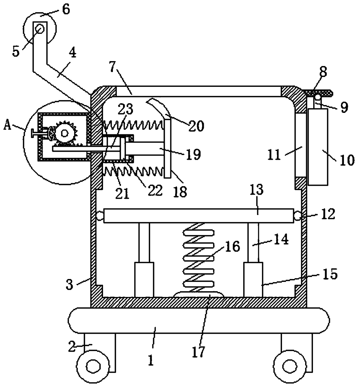
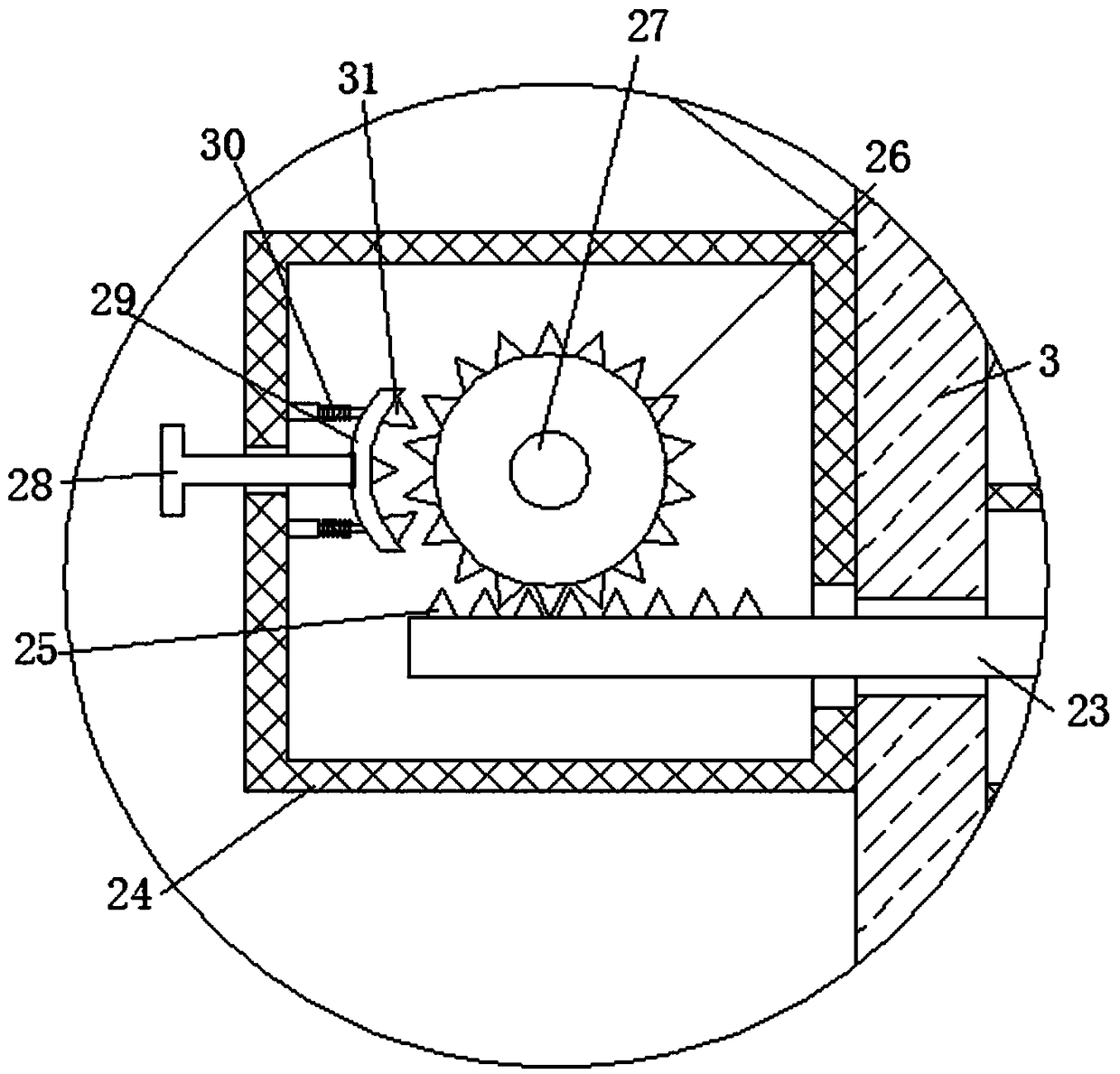
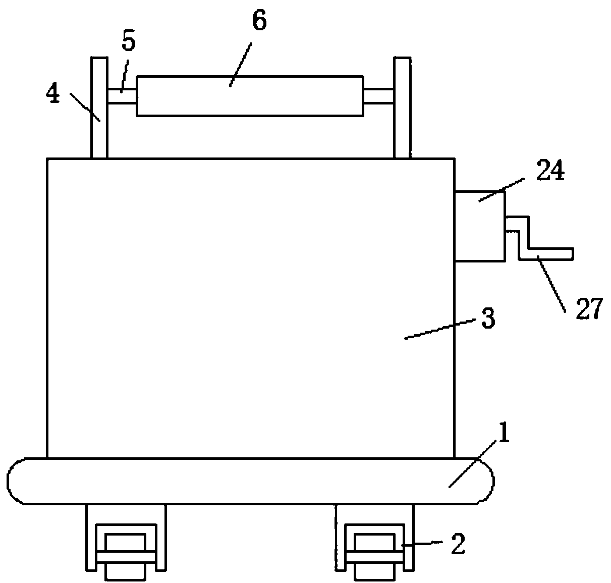
[0030] see Figure 1-3 , the present invention provides a technical solution:

[0031] A conveying device for lightweight building materials with a clamping function, comprising a base 1, the upper end of the base 1 is fixedly connected with a conveying box 3, and the upper end of the conveying box 3 is provided with a first placement opening 7, and the inner bottom of the conveying box 3 The wall is fixedly connected with a plurality of guide cylinders 15, a...


PUM


Abstract

The invention discloses a conveying device provided with a clamping fixing function and used for a light building material. Multiple guide barrels are fixedly connected to the inner bottom wall of a conveying box, guide rods are connected into the guide barrels in a sliding mode, the upper ends of the guide rods are fixedly connected to the lower end face of a bearing plate, the lower end of the bearing plate is fixedly connected with one end of a buffer spring, the other end of the buffer spring is fixedly connected to the upper end face of a spring seat, a clamping plate moves to drive eachfixed tooth to enter the position between two corresponding teeth of a gear, and therefore a limiting effect is achieved. Due to the existence of the combination of a first containing port and a second containing port, the effect that the building material is convenient to take and place can be achieved. Due to the existence of the combination of a fixed plate, a hinged rod and a blocking plate, the effect that the second containing port is blocked can be achieved. Therefore, the conveying device can achieve the effect that the building material is prevented from being placed in disorder.

Description

technical field [0001] The invention relates to the technical field of building materials, in particular to a conveying device for lightweight building materials with a clamping function. Background technique [0002] Lightweight building materials need to be frequently transported during the manufacturing process. The existing transport vehicles for transporting building materials have some defects. The arm cannot directly place the material in the corresponding position, and the material will fall directly into the storage box after leaving the hand, which is easy to cause damage to fragile items, and correspondingly, it will be inconvenient when picking up the material. And when the box full of materials is transported, it is easy to cause damage to the materials due to the bumps on the road surface. There is only one outlet, and there is only the top, so that the placement and removal of building materials must be realized through the top inlet and outlet, which makes i...

Claims


Application Information

Patent Timeline
Patent Type & Authority Applications(China)
IPC IPC(8): B62B3/04B62B5/00
CPCB62B3/04B62B5/00B62B2202/00
Inventor 黄洋
Owner 赣阳建工集团有限公司
Why Eureka
Try Eureka