
Pressure relief device

A pressure relief device and pressure relief technology, applied in valve devices, lift valves, safety valves, etc., can solve the problems of unstable operation and low service life, and achieve the effect of stable operation, long service life and avoiding aging.

Inactive Publication Date: 2018-11-30
SHANGHAI NEUSOFT MEDICAL TECH LTD
View PDF12 Cites 2 Cited by
  • Summary
  • Abstract
  • Description
  • Claims
  • Application Information

AI Technical Summary

Problems solved by technology

[0003] The pressure relief device provided in the related art has the defects of unstable operation and low service life

Method used


Image

  • Pressure relief device
  • Pressure relief device
  • Pressure relief device

Examples


Embodiment Construction

[0057] Reference will now be made in detail to the exemplary embodiments, examples of which are illustrated in the accompanying drawings. When the following description refers to the accompanying drawings, the same numerals in different drawings refer to the same or similar elements unless otherwise indicated. The implementations described in the following exemplary embodiments do not represent all implementations consistent with this application. Rather, they are merely examples of apparatuses and methods consistent with aspects of the present application as recited in the appended claims.

[0058] The terminology used in this application is for the purpose of describing particular embodiments only, and is not intended to limit the application. As used in this application and the appended claims, the singular forms "a", "the", and "the" are intended to include the plural forms as well, unless the context clearly dictates otherwise. It should also be understood that the term...


PUM


Abstract

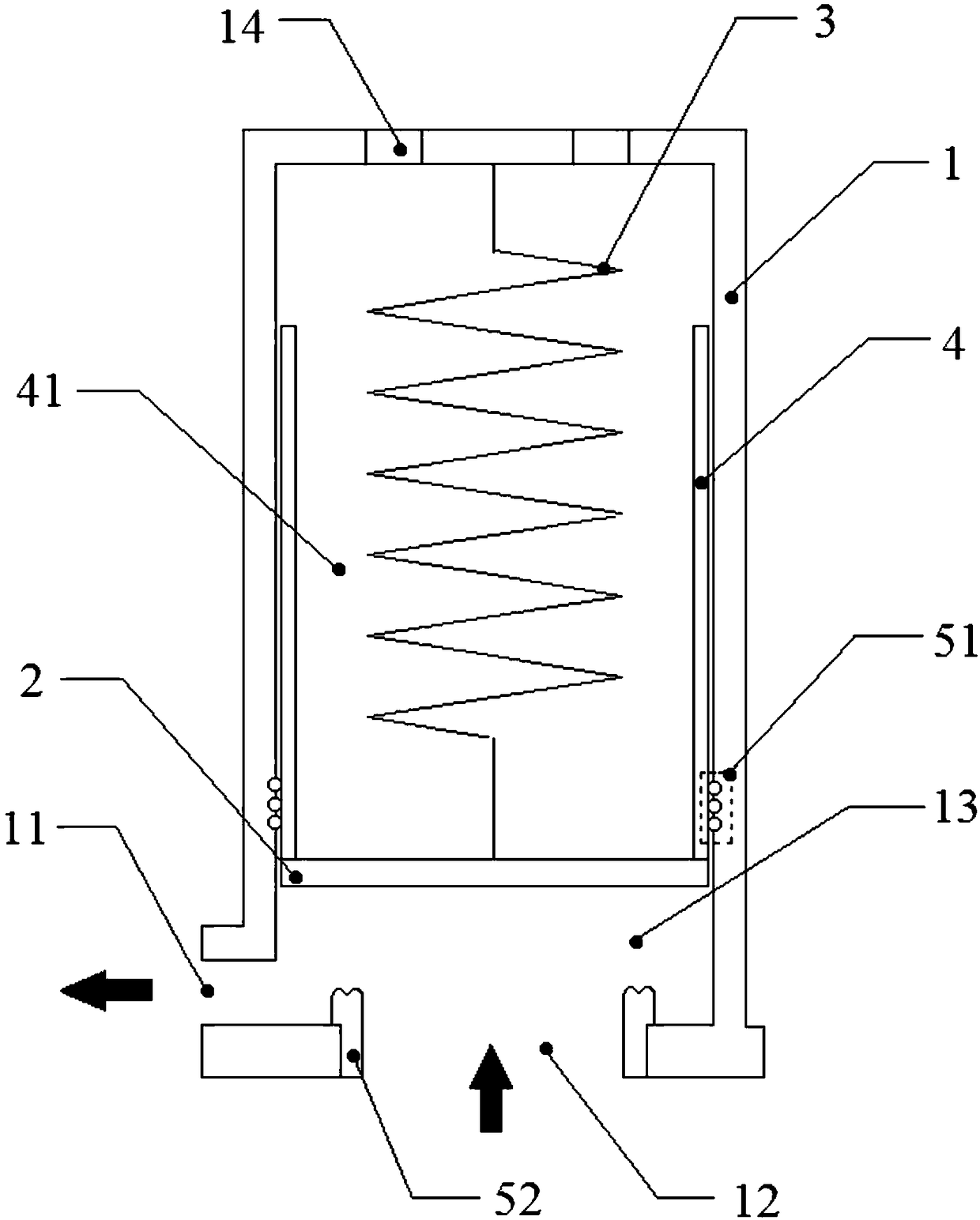
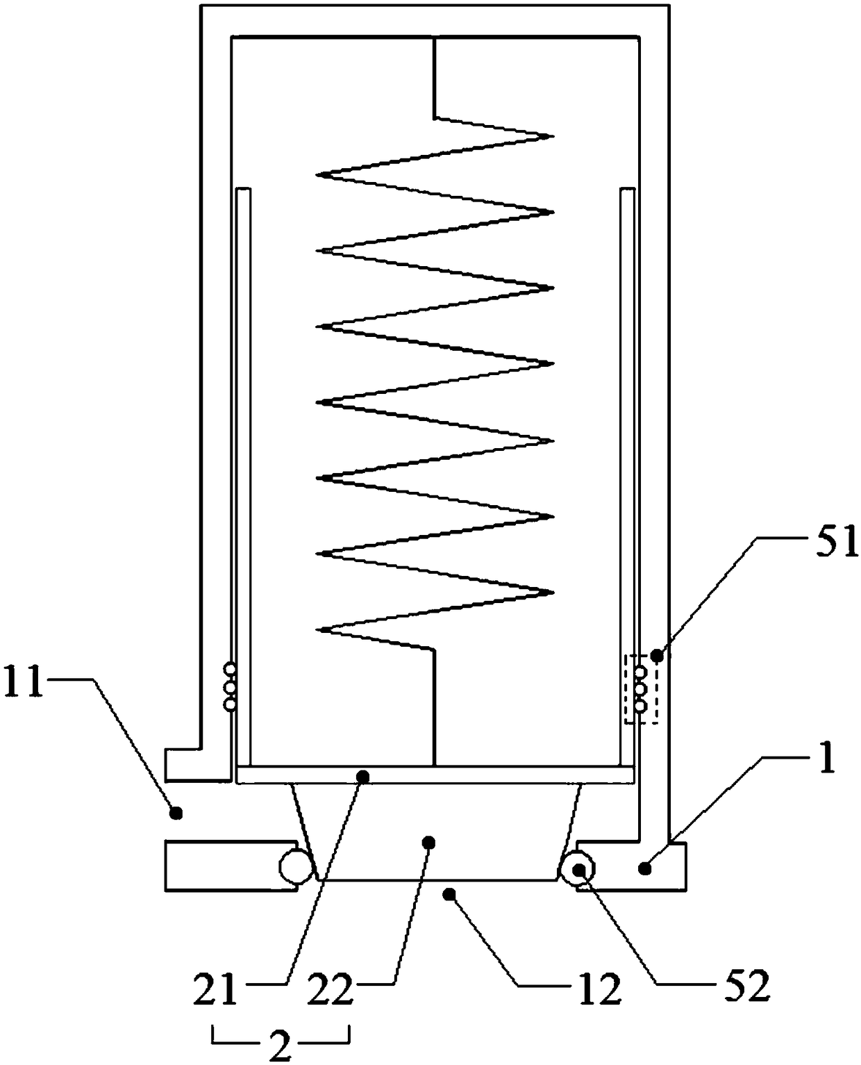
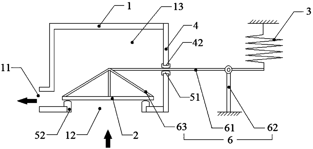
The invention provides a pressure relief device, and belongs to the technical field of superconducting magnets. The pressure relief device comprises a body, a movable piece, an elastic piece and a protecting piece; the body comprises a pressure relief opening; the movable piece has a first position and a second position which can be switched over; when the movable piece is located at the first position, a high-pressure chamber is isolated from the pressure relief opening; when the movable piece is located at the second position, the high-pressure chamber communicates with the pressure relief opening; the elastic piece acts on the movable piece, and thus, the movable piece moves to the first position from the second position or stops at the first position; and the protecting piece stops theelastic piece from being in contact with fluid which flows to the pressure relief opening from the high-pressure chamber. By the protecting piece, the elastic piece is isolated from the fluid which flows to the pressure relieve opening from the high-pressure chamber is stopped, and the circumstance that the fluid is in contact with the elastic piece to result in loss of part of functions of the elastic piece. By the protecting piece, a stable working environment is provided for the elastic piece, acceleration of ageing of the elastic piece is avoided, and thus, the whole pressure relieve device runs stably, and has long service life.

Description

technical field [0001] The present application relates to the technical field of superconducting magnets, in particular to a pressure relief device. Background technique [0002] A superconducting magnet is a device that uses liquid helium as a refrigerant to achieve superconducting operation at low temperatures. Superconducting magnets require large quantities of liquid helium to operate and are therefore usually equipped with refrigerant supply tanks. During the use of superconducting magnets, there may be special circumstances that cause the gas phase of liquid helium to change, which increases the volume of gaseous helium in the refrigerant supply tank and the pressure in the tank rises sharply. At this time, it is necessary to install a pressure relief device on the refrigerant supply tank to release the gas in the refrigerant supply tank to ensure the safety of the equipment. [0003] The pressure relief device provided in the related art has the defects of unstable ...

Claims


Application Information

Patent Timeline
IPC IPC(8): F16K17/04F16K1/46
CPCF16K1/46F16K17/04F16K17/0413
Inventor 杨英福杨磊王赞明
Owner SHANGHAI NEUSOFT MEDICAL TECH LTD
Learn More