Rotation limiting structure and handheld pan-tilt

A limited structure, hand-held pan-tilt technology, applied in the field of pan-tilt, to achieve the effect of convenient operation and simple structure

Pending Publication Date: 2018-11-30
智卓(深圳)电子科技有限公司
0 Cites 5 Cited by

AI-Extracted Technical Summary

Problems solved by technology

[0003] In view of this, it is necessary to provide a rotation limiting structure and a handheld platform, which ca...

Abstract

A rotation limiting structure is applied to a handheld pan-tilt. The handheld pan-tilt comprises a first rotating part and a second rotating part which can rotate relative to each other, and the rotation limiting structure is arranged between the first rotating part and the second rotating part. The rotation limiting structure comprises a first limiting part and a second limiting part, wherein thefirst limiting part is arranged on the first rotating part, and the second limiting part is arranged on the second rotating part. The first limiting part comprises a limiting protrusion, the second limiting part comprises a limiting groove, and the limiting protrusion can enter the limiting groove to lock the relative rotation between the first rotating part and the second rotating part. Under the action of external force, the limiting protrusion can be withdrawn from the limiting groove so that the first rotating part and the second rotating part can freely rotate. The rotation limiting structure is simple and convenient to operate, and the problem about free rotation of a stabilizing mechanism of the handheld pan-tilt in a non-working state can be solved.

Application Domain

Stands/trestles

Technology Topic

EngineeringFree rotation

Image

  • Rotation limiting structure and handheld pan-tilt
  • Rotation limiting structure and handheld pan-tilt
  • Rotation limiting structure and handheld pan-tilt

Examples

  • Experimental program(1)

Example Embodiment

[0020] The technical solutions in the embodiments of the present invention will be clearly and completely described below with reference to the accompanying drawings in the embodiments of the present invention. Obviously, the described embodiments are only a part of the embodiments of the present invention, but not all of the embodiments. Based on the embodiments of the present invention, all other embodiments obtained by those of ordinary skill in the art without creative efforts shall fall within the protection scope of the present invention.
[0021] It should be noted that when a component is referred to as being "fixed to" another component, it can be directly on the other component or there may also be a centered component. When a component is considered to be "connected" to another component, it may be directly connected to the other component or there may be a co-existence of an intervening component. When a component is considered to be "set on" another component, it may be directly set on the other component or there may be a co-existing centered component. The terms "vertical," "horizontal," "left," "right," and similar expressions are used herein for illustrative purposes only.
[0022] Unless otherwise defined, all technical and scientific terms used herein have the same meaning as commonly understood by one of ordinary skill in the art to which this invention belongs. The terms used herein in the description of the present invention are for the purpose of describing specific embodiments only, and are not intended to limit the present invention. As used herein, the term "and/or" includes any and all combinations of one or more of the associated listed items.
[0023] In order to make the above objects, features and advantages of the present invention more clearly understood, the specific embodiments of the present invention will be described in detail below with reference to the accompanying drawings. The embodiments of the present invention are described in detail with reference to the schematic diagrams. When describing the embodiments of the present invention in detail, for the convenience of explanation, the diagrams representing the partial structures of the devices will not be partially enlarged according to the general scale, and the schematic diagrams are only examples, which are not described here. The scope of protection of the present invention should be limited.
[0024] The handheld pan/tilt provided by the embodiment of the present invention is used to carry camera devices such as mobile phones, tablets, cameras, and video cameras, so as to realize the fixation and attitude adjustment of the camera device (for example, changing the height, inclination angle and/or change of the camera device) direction) and keep the camera device stably in a certain attitude. The hand-held cloud platform of the present invention will be described in detail below with reference to the accompanying drawings.
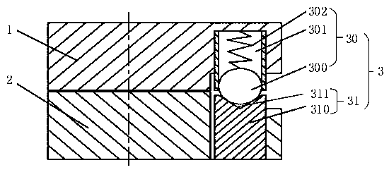
[0025] The handheld cloud platform provided by the present invention includes a first rotating part and a second rotating part, and the first rotating part and the second rotating part can rotate relative to each other. The first rotating part and the second rotating part are any relative rotatable components on the handheld platform. For example, when the handheld platform is a two-axis platform, the first rotating part and the second rotating part The parts can be the rotor assembly and the stator assembly of the first shaft, respectively, and can also be the stator assembly and the rotor assembly of the second shaft. When the handheld gimbal is a three-axis gimbal, the first rotating part and the second rotating part can be a rotor assembly and a stator assembly of any one of the three axes.
[0026] When the handheld cloud platform is in the working state, the first rotating part and the second rotating part can rotate relative to each other under the driving of an external force (for example, the driving force of the rotating shaft drive motor), so as to adjust the installation on the handheld cloud platform. The shooting angle of the camera at the end of the stage. When the handheld gimbal is in a non-working state, free rotation may occur between the first rotating part and the second rotating part. In order to control the distance between the first rotating part and the second rotating part No relative rotation occurs, and the present invention provides a rotation restricting structure capable of allowing a user to lock the relative rotation between the first rotating part and the second rotating part. The rotation restriction structure is arranged between the first rotation part and the second rotation part, and includes: a first limit part arranged on the first rotation part and a first stop part arranged on the second rotation part. Two limit parts, wherein the first limit part includes a limit protrusion, the second limit part includes a limit groove, and the limit protrusion can enter the limit groove to lock the limit The relative rotation between the first rotating part and the second rotating part, under the action of external force, the limiting protrusion can be withdrawn from the limiting convex groove, so that the first rotating part and the second rotating part able to rotate freely.
[0027] figure 1 A schematic diagram of a rotation limiting structure according to an embodiment of the present invention is shown. The rotation restricting structure 3 is disposed between the first rotating part 1 and the second rotating part 2 for restricting the relative rotation between the first rotating part 1 and the second rotating part 2 . The rotation limiting structure 3 includes a first limiting portion 30 provided on the first rotating portion 1 and a second limiting portion 31 provided on the second rotating portion 2 .
[0028] The first limiting portion 30 is fixed on the first rotating portion 1 , and a positioning cavity 301 is provided therein, and the limiting protrusion 300 is disposed in the positioning cavity 301 through an elastic member 302 . The second limiting portion 31 is fixed on the second rotating portion 2 , and includes a limiting block 310 fixed on the second rotating portion 2 , and a limiting groove 311 is opened on the limiting block 310 In the direction facing the first rotating part 1 , the shape of the limiting groove 311 is adapted to the shape of the limiting protrusion 300 .
[0029] By applying external force to rotate the first rotating part 1 relative to the second rotating part 2, when the limiting protrusion 30 moves to the position corresponding to the limiting groove 32, the limiting protrusion 300 The limiting groove 311 can be entered under the resistance of the elastic member 302 , thereby locking the relative rotation between the first rotating part 1 and the second rotating part 2 . When an external force is applied again to rotate the first rotating part 1 relative to the second rotating part 2, the limiting protrusion 300 exits the limiting groove 311, the elastic member 302 is compressed, and the limiting protrusion 300 is compressed. The positioning protrusion 300 is limited in the positioning cavity 301 , and the first rotating part 1 can freely rotate relative to the second rotating part 2 .
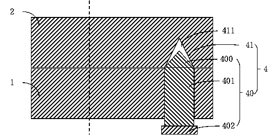
[0030] In the embodiment shown in the figure, the limiting protrusion 300 is a spherical ball, and the positioning cavity 301 is a cylindrical blind hole, the diameter of which is slightly larger than the diameter of the ball. The limiting groove 311 may be in a shape capable of accommodating the limiting protrusion 300 , such as a circular hole, and the diameter of the circular hole is slightly larger than the diameter of the ball. It can be understood that, in other embodiments, the limiting groove 311 can also be any other suitable shape, such as a conical groove. It can be understood that, in other embodiments, the limiting protrusion 300 can also be any suitable shape, such as a cylindrical shape with an inclined surface, a cylindrical shape with an arc surface, and the like. Correspondingly, the limiting groove 311 is also in a shape suitable for the limiting protrusion 300 , so that the limiting protrusion 300 can enter or exit the limiting groove 311 .
[0031] It can be understood that, in some embodiments, the limiting block 310 may be omitted, and the limiting groove 311 is directly formed on the second rotating part 2 .
[0032] see figure 2 As shown, it is a schematic structural diagram of another rotation limiting structure 4 provided by the present invention. The rotation limiting structure 4 includes a first limiting portion 40 provided on the first rotating portion 1 and a second limiting portion 42 provided on the second rotating portion 2 .
[0033] The first limiting portion 40 includes a threaded portion 401. The limiting protrusion 400 extends from the threaded portion 401 to the second rotating portion 2. Under the action of an external force, the threaded portion 401 can drive the limiting portion 401. The protrusion 400 moves toward the limiting groove 411 so that the limiting protrusion 400 enters the limiting groove 411 to lock the mutual relationship between the first rotating part 1 and the second rotating part 2 . turn.
[0034] In the embodiment shown in the figure, the first rotating part 1 is provided with an internal thread hole, and the thread part 401 cooperates with the internal thread of the internal thread hole so as to be screwed or screwed in the internal thread hole. out. It can be understood that, in other embodiments, the first limiting portion 40 may include a limiting column, the limiting column is fixedly arranged on the first limiting portion, and the limiting column is provided with Internal thread hole, the threaded portion 401 is disposed in the internal thread hole, and can move toward or away from the second rotating portion in cooperation with the internal thread of the internal thread hole.
[0035] The first limiting portion 40 further includes an operating portion 402, the operating portion 402 is disposed at the end of the threaded portion 401 away from the limiting protrusion 400, and is used for applying an external force to make the threaded portion 401 face the desired position. The direction of the limit groove is precessed. The operating portion 402 is rotated by an external force and the threaded portion 401 moves toward the limiting groove 411. When the limiting protrusion 400 enters the positioning groove 411 driven by the threaded portion 401, it can move toward the limiting groove 411. The relative rotation between the first rotating part 1 and the second rotating part 2 is locked. When the operating portion 402 is reversely rotated, the threaded portion 401 moves away from the limiting groove 411 , thereby driving the limiting protrusion 400 to withdraw from the limiting groove 411 to unlock the first In the relative rotation between the rotating part 1 and the second rotating part 2, the first rotating part 1 and the second rotating part 2 can rotate with each other at this time.
[0036] It can be understood that, in other embodiments, the operating part 402 can also be replaced with other structures, for example, the rotation of the threaded part 401 relative to the second rotating part 2 is automatically controlled by means of screw driving.
[0037] The limiting protrusions 400 may be conical or cylindrical, and the shape of the limiting grooves 411 is adapted to the shape of the limiting protrusions 400 . It can be understood that, in other embodiments, the limiting protrusion 400 can also be any other suitable regular or irregular shape, and the shape of the limiting groove 411 is the same as the shape of the limiting protrusion 400 . It is suitable as long as the limiting protrusion 400 can enter and exit the limiting groove 411 along with the movement of the threaded portion 401 .
[0038] The handheld pan/tilt head provided by the present invention includes a first rotating part, a second rotating part, and a rotation restricting structure arranged between the first rotating part and the second rotating part, and the rotation restricting structure may be an upper The rotation restricting structure 3 or the rotation restricting structure 4 is described. The handheld gimbal can be a single-axis gimbal, a two-axis gimbal or a three-axis gimbal. The rotation restricting structure may be provided on either a two-axis or a three-axis rotation mechanism. The following description will be given by taking a three-axis handheld pan/tilt as an example, wherein the three-axis handheld pan/tilt includes a rotation limiting structure 3 .
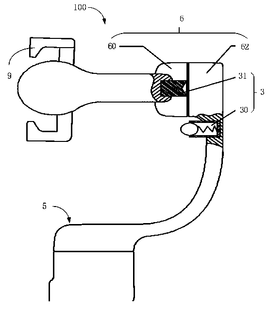
[0039] see Figure 3 to Figure 5 As shown, it is a schematic structural diagram of a handheld gimbal 100 provided by the present invention. The handheld gimbal 100 is a three-axis gimbal, including a first rotating shaft mechanism 5 , a second rotating shaft mechanism 6 and a third rotating shaft mechanism 7 . The third rotating shaft mechanism 7 is connected with a clamping mechanism 9, and the clamping mechanism 9 is used for clamping the photographing device. The first rotating shaft mechanism 5 , the second rotating shaft mechanism 6 and the third rotating shaft mechanism 7 can all be provided with the rotating shaft limiting structure 3 or 4 . For the convenience of description, the second rotating shaft mechanism 6 is taken as an example for description. The second rotating shaft mechanism 6 includes a rotor 60 and a stator 62 , and the rotor 60 can rotate relative to the stator 62 under the driving of the rotating shaft motor of the second rotating shaft mechanism. The rotation restricting structure 3 is provided on the second rotating shaft mechanism 6 , wherein one of the rotor 60 and the stator 62 can be used as a first rotating part, and the other can be used as a second rotating part. In the figure, the stator 62 is used as the first rotating part, and the first limiting part 30 is provided on the stator 62; the rotor 60 is used as the second rotating part, and the second limiting part 31 is provided on the on the rotor 60. see image 3 , 4 , is the state in which the limiting protrusion 300 is separated from the limiting groove 311 , and at this time, the rotation limiting structure 3 is in an unlocked state, and the rotor 60 can freely rotate relative to the stator 62 . see Figure 5 As shown, the limiting protrusion 300 enters the limiting groove 311 , and the rotation limiting structure 3 is in a locked state. At this time, the rotor 60 cannot freely rotate relative to the stator 62 .
[0040] The hand-held pan/tilt also includes a controller (not shown), and a position sensor (not shown) disposed on the limit protrusion or the limit groove, the position sensor is connected with the position sensor. The controller is connected, and when the limiting protrusion is locked in the limiting groove, the controller controls the handheld pan/tilt to enter a standby state according to the position signal of the position sensor; when When the limiting protrusion is withdrawn from the limiting groove, the controller controls the handheld pan/tilt to enter a working state according to the position signal of the position sensor.
[0041] For the gimbal without the rotation restriction structure, the user needs to carry a storage bag (box) suitable for the gimbal in general use situations. When the user does not need to use the gimbal, place the gimbal in the storage bag (box). In order to ensure that the gimbal will not shake randomly during the user's carrying process; when the gimbal is used again, it is necessary to take the gimbal out of the storage bag (box) and restart the gimbal before it can be used. For the gimbal equipped with the rotation restricting structure of the present invention, after the rotation restricting structure in the gimbal cooperates, the rotor and stator of the rotating shaft mechanism of the handheld gimbal can no longer rotate freely, and the user does not need to worry about the gimbal when carrying the gimbal. Trouble with free rotation of components. At the same time, if the user forces the rotation limiting structure to reach the locked position during the normal operation of the gimbal, the gimbal will not malfunction and other abnormalities, and the gimbal will enter a standby state, which consumes very little energy. When the user uses the gimbal again, there is no need to restart the gimbal through the power control button of the gimbal again, just unlock the gimbal from the locked state of the rotation restriction structure, and the gimbal can resume normal operation. This makes it convenient for users to quickly use the gimbal anytime, anywhere.
[0042] In addition, for those of ordinary skill in the art, various other corresponding changes and deformations can be made according to the technical concept of the present invention, and all these changes and deformations should belong to the protection scope of the claims of the present invention.

PUM

no PUM

Description & Claims & Application Information

We can also present the details of the Description, Claims and Application information to help users get a comprehensive understanding of the technical details of the patent, such as background art, summary of invention, brief description of drawings, description of embodiments, and other original content. On the other hand, users can also determine the specific scope of protection of the technology through the list of claims; as well as understand the changes in the life cycle of the technology with the presentation of the patent timeline. Login to view more.

Similar technology patents

Body condition measuring device

InactiveUS20050234351A1simple structure
Owner:DENSO CORP

Magnetic cooling apparatus and control method thereof

ActiveUS20130180263A1simple structure
Owner:SAMSUNG ELECTRONICS CO LTD

Dual-Drivetrain of Power-Assist Vehicle

InactiveUS20100181130A1enhance uphill momentumsimple structure
Owner:CHOU WEN CHENG

Classification and recommendation of technical efficacy words

  • Simple structure
  • easy to operate

Sharing system for air-conditioning coat

InactiveCN107440179ASimple structureeasy to wear
Owner:QINGDAO HAIER AIR CONDITIONER GENERAL CORP LTD

Feeding device of sorter of batteries plate

InactiveCN101357717ASimple structurecooperate well
Owner:NANJING NORMAL UNIVERSITY

Emergency parachuting device and method for multiple-rotor unmanned aerial vehicle

InactiveCN103895870Aavoid aircraft crashSimple structure
Owner:SOUTH CHINA AGRI UNIV +1

Lancet device

InactiveUS7303573B2inexpensively mass-producedeasy to operate
Owner:ABBOTT DIABETES CARE INC

Rapid and non-invasive optical detection of internal bleeding

InactiveUS20050065436A1easy to operaterapid and accurate result
Owner:HO WINSTON ZONH +2
Why Eureka
Try Eureka