
Demura multi-axis full-automatic detection mechanism

A detection mechanism, fully automatic technology, applied in the direction of optical testing flaws/defects, etc., can solve the problems of CCD cameras that cannot meet the test accuracy, no open automatic detection mechanism, inaccurate focus, etc., to achieve simple structure, reduced volume and Quality, the effect of improving focusing accuracy

Pending Publication Date: 2018-11-30
WUHAN JINGCE ELECTRONICS GRP CO LTD
View PDF6 Cites 2 Cited by
  • Summary
  • Abstract
  • Description
  • Claims
  • Application Information

AI Technical Summary

Problems solved by technology

The above-mentioned technical solution has the following technical problems: First, the invention does not disclose a complete technical solution for an automatic detection mechanism. According to the description of the above-mentioned comparative document, it is only known that the CCD camera has three degrees of freedom, and what does the CCD camera rely on? The driver has not been made public; secondly, if the adjustment mechanism is used to adjust the position and height of the CCD camera to achieve focus adjustment, the focus will inevitably be inaccurate due to the large amplitude adjustment, and may also cause damage to the camera; finally, the three-degree-of-freedom CCD camera cannot meet the Mura requirements. The required test accuracy of the compensation system

Method used


Image

  • Demura multi-axis full-automatic detection mechanism
  • Demura multi-axis full-automatic detection mechanism
  • Demura multi-axis full-automatic detection mechanism

Examples


Embodiment Construction

[0020] In order to make the object, technical solution and advantages of the present invention clearer, the present invention will be described in further detail below in conjunction with the accompanying drawings and embodiments. It should be understood that the specific embodiments described here are only used to explain the present invention, not to limit the present invention.

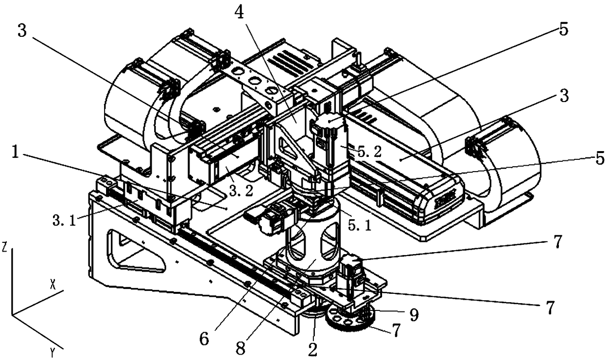
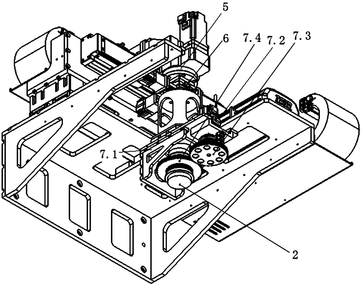
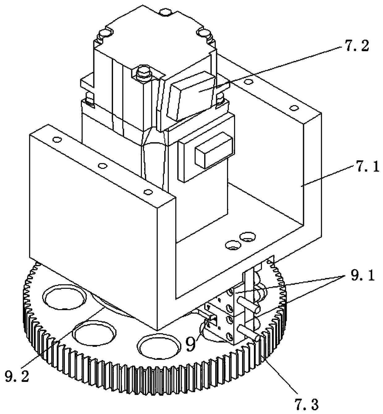
[0021] attached by the manual Figure 1-2A kind of Demura multi-axis automatic detection mechanism shown can be known, and it comprises frame 1 and CCD camera 2, and frame 1 is provided with and is used to drive the slide module 3 that CCD camera 2 moves along horizontal X-axis and Y-axis, The movable end of the slide module 3 is connected to a connecting frame 4, and the CCD camera 2 is connected to the lower part of the connecting frame 4; between the connecting frame 4 and the CCD camera 2, there are sequentially arranged a set for driving the CCD camera 2 around the vertical Z axis from top to ...


PUM


Abstract

The invention discloses a Demura multi-axis full-automatic detection mechanism. The Demura multi-axis full-automatic detection mechanism comprises a stander and a CCD camera, wherein the stander is provided with a sliding table module, the movable end of the sliding table module is connected with a connecting frame, and the CD camera is connected to the bottom of the connecting frame; a rotary carrying table mechanism, a swinging sliding table and a gear focusing mechanism are successively arranged between the connecting frame and the CCD camera from top to bottom; the gear focusing mechanismcomprises a foundation support, a second drive source, a driving gear and a driven gear; and the rotary carrier table mechanism, the swinging sliding table and the CCD camera are coaxially distributed. Compared with the traditional Demura detection mechanism, the Demura multi-axis full-automatic detection mechanism is simple in structure and convenient in use; the CCD camera can move along the directions of an X axis, a Y axis and a Z axis and can also rotate around the X, Y and Z axis, so that the full-automatic adjustment can be realized; and moreover, the Demura multi-axis full-automatic detection mechanism is provided with a focal length adjusting mechanism, and the inaccuracy in focusing and damage of the camera caused by the large adjustment amplitude of the CCD camera along the Z axis direction can be avoided.

Description

technical field [0001] The invention relates to a Demura detection mechanism, which belongs to the technical field of display panel detection, in particular to a Demura multi-axis automatic detection mechanism. Background technique [0002] In recent years, with the rapid popularization of household TVs, consumers have higher and higher requirements for LCD TV screens, so the quality of LCD TV screens is also getting higher and higher. Due to the complex production process and difficult control of LCD TV display panels, it is easy to cause Mura phenomenon (uneven brightness) during the production process, and bright or dark spots appear, that is, blocks caused by differences in display brightness in a certain area of ​​the panel Like trace phenomenon, reduce the quality level of the panel. In order to eliminate the above-mentioned Mura phenomenon, Demura (elimination of panel brightness unevenness) technology came into being. [0003] Demura technology is a technology that...

Claims


Application Information

Patent Timeline
Patent Type & Authority Applications(China)
IPC IPC(8): G01N21/88
CPCG01N21/88
Inventor 罗军龚四羊乔洁
Owner WUHAN JINGCE ELECTRONICS GRP CO LTD
Learn More