Independent gas supply pneumatic system capable of providing pneumatic muscles for working

A pneumatic system and pneumatic muscle technology, applied in the field of pneumatic systems, can solve problems such as unfavorable integration in mobile robots, and achieve the effects of compact structure, reduced volume, reduced volume and quality

Active Publication Date: 2016-05-25
HARBIN INST OF TECH
View PDF6 Cites 4 Cited by
  • Summary
  • Abstract
  • Description
  • Claims
  • Application Information

AI Technical Summary

Problems solved by technology

[0004] The purpose of the present invention is to solve the problem that the existing pneumatic system requires a large-volume cylinder to store high-pressure gas, and the pneumatic muscle is inflated and exhausted th

Method used


Image

  • Independent gas supply pneumatic system capable of providing pneumatic muscles for working
  • Independent gas supply pneumatic system capable of providing pneumatic muscles for working

Examples


specific Embodiment approach 1

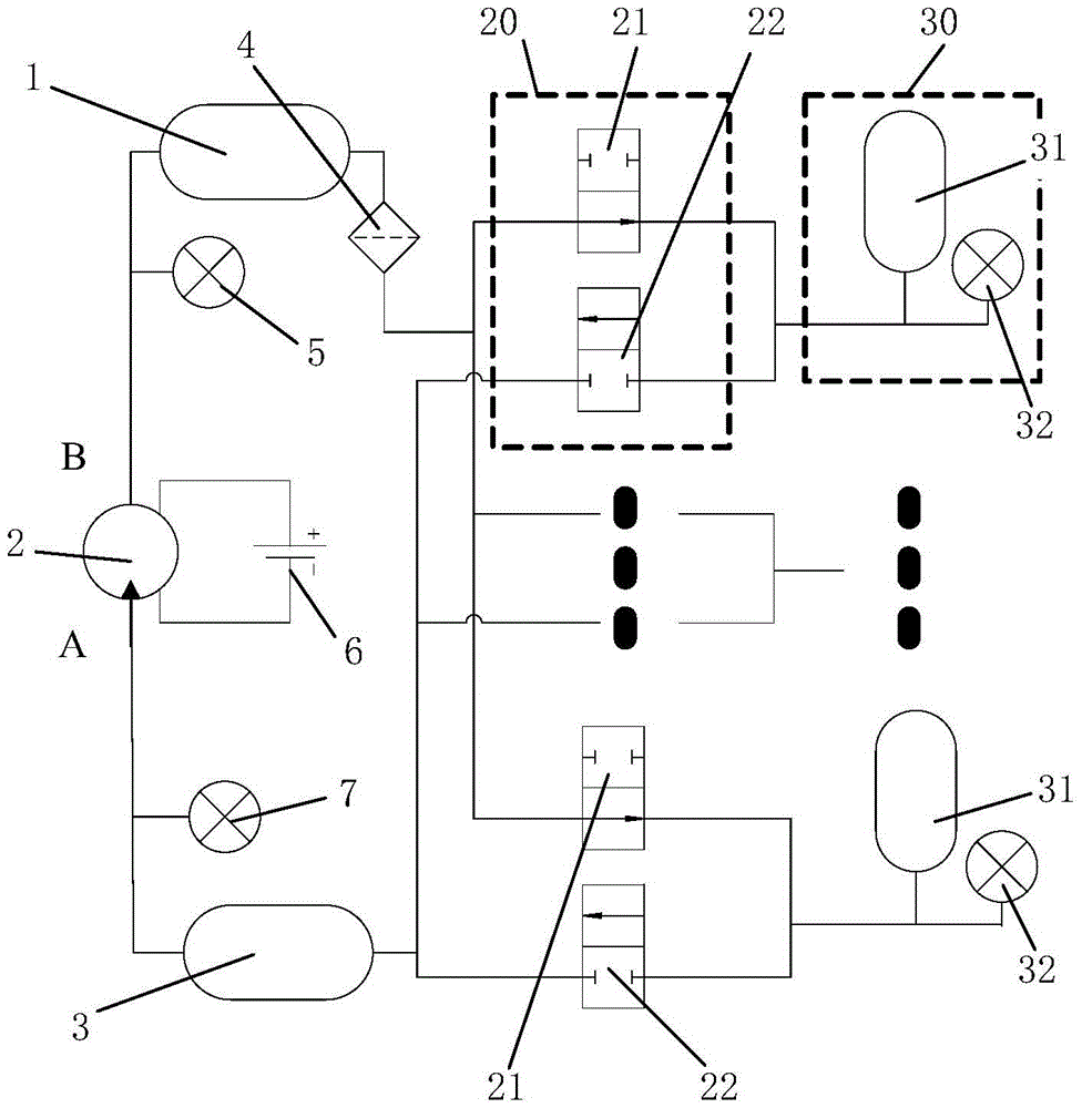
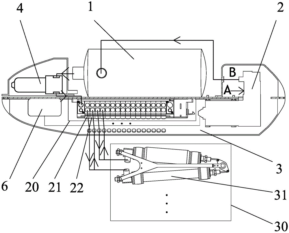
[0014] Specific implementation mode one: combine Figure 1 to Figure 2 Describe this embodiment, this embodiment is an independent air supply pneumatic system that provides pneumatic muscle work, it includes a hyperbaric chamber 1, an air pump 2, a low pressure chamber 3, an air filter valve 4, a hyperbaric chamber pressure sensor 5, a battery 6, and a low pressure chamber The pressure sensor 7, the switch pneumatic system 20 and the pneumatic actuator unit 30, the hyperbaric chamber 1 and the low pressure chamber 3 are arranged oppositely and the hyperbaric chamber 1 and the low pressure chamber 3 are connected through the air pump 2, and the battery 6 is connected to the air pump 2 and supplies power for the air pump 2 , the hyperbaric chamber 1 is connected to the air filter valve 4 and provides an air source for the pneumatic muscle 31 of the pneumatic actuator 30 through the intake high-speed switching valve 21 in the switching pneumatic system 20, and the low-pressure cha...

specific Embodiment approach 2

[0018] Specific implementation mode two: combination Figure 1 to Figure 2 Describe this embodiment, the air inlet A end of the air pump 2 of this embodiment is connected to the low pressure chamber 3 , and the exhaust port B end of the air pump 2 is connected to the hyperbaric chamber 1 . Such setting: it is convenient to realize the pressure difference between the hyperbaric chamber and the low pressure chamber, so that the pneumatic system of the present invention is isolated from the external atmosphere, forming an independent air source that can be integrated. Other compositions and connections are the same as those in the second embodiment.

specific Embodiment approach 3

[0019] Specific implementation mode three: combination Figure 1 to Figure 2 Describe this embodiment, the switching pneumatic system 20 of this embodiment comprises intake high-speed switch valve 21 and exhaust high-speed switch valve 22, and intake high-speed switch valve 21 and exhaust high-speed switch valve 22 are arranged in parallel and with air filter valve 4 or Low pressure chamber 3 connection. The benefit of such setting is that it is convenient to reduce the volume. Other compositions and connections are the same as those in the second embodiment.


PUM


Abstract

The invention discloses an independent gas supply pneumatic system capable of providing pneumatic muscles for working, and relates to a pneumatic system. The invention aims to solve the problem that an existing pneumatic system needs a large-volume cylinder to store high-pressure gas and the pneumatic muscles are inflated and exhausted by pressure proportional valve pressure-regulating equipment, so that the pneumatic system cannot be integrated into a mobile robot by reducing a volume and a mass of the pneumatic system. According to the independent gas supply pneumatic system disclosed by the invention, a high pressure cabin and a low pressure cabin are arranged oppositely and are communicated by a gas pump; a battery is connected to the gas pump and supplies power to the gas pump; the high pressure cabin is connected with an air filtering valve and provides a gas source for a pneumatic execution unit by one switching pneumatic system; the low pressure cabin provides an exhaust space for the pneumatic execution unit by another switching pneumatic system; a high-pressure-cabin pressure sensor is used for measuring an in-cabin pressure of the high pressure cabin; a low-pressure-cabin pressure sensor is used for measuring an in-cabin pressure of the low pressure cabin. The independent gas supply pneumatic system is particularly suitable for a frog swimming simulation robot.

Description

technical field [0001] The invention relates to a pneumatic system that can be integrated on a mobile robot body, in particular to an independent air supply pneumatic system that provides pneumatic muscle work. Background technique [0002] Pneumatic muscles are widely used in robot drives due to their light weight, small size, large output force, and passive compliance. However, pneumatic components generally require large and heavy air sources, processing equipment, and pressure regulating systems. For this reason, it is of great significance to design a pneumatic system that can be integrated in the robot body and has a small size. [0003] Conventional pneumatic systems require large-volume cylinders to store high-pressure gas, and the pneumatic muscles are inflated and exhausted through pressure regulating devices such as pressure proportional valves. However, pressure regulating devices such as pressure proportional valves are large in volume and mass, which is not con...

Claims


Application Information

Patent Timeline
IPC IPC(8): B25J9/14
CPCB25J9/142
Inventor 樊继壮赵杰张伟孔彭城
Owner HARBIN INST OF TECH
Why Eureka
Try Eureka