
Hot stamping forming device for high-strength steel

A technology of hot stamping and high-strength steel, which is applied in the direction of forming tools, feeding devices, positioning devices, etc., can solve the problems of low work efficiency, inconvenient and time-consuming demolding of formed parts, and achieve high stamping efficiency and processing efficiency High, guaranteed continuity effect

Active Publication Date: 2019-07-16
DONGFENG WUHAN IND
View PDF6 Cites 0 Cited by
  • Summary
  • Abstract
  • Description
  • Claims
  • Application Information

AI Technical Summary

Problems solved by technology

[0003] The existing hot stamping forming device is time-consuming and cumbersome, after heating the billet, manually or with a robot to clamp the heated billet into the stamping die for stamping, which is time-consuming and troublesome, and the billet placed on the stamping table is unstable. The problem is that it is not convenient to demould the molded parts after stamping is completed, and manual or mechanical hand is required for demoulding. This kind of hot stamping forming device is time-consuming and has low work efficiency

Method used


Image

  • Hot stamping forming device for high-strength steel
  • Hot stamping forming device for high-strength steel
  • Hot stamping forming device for high-strength steel

Examples


Embodiment Construction

[0038] The present invention will be further described in detail below in conjunction with the accompanying drawings, so that those skilled in the art can implement it with reference to the description.

[0039] It should be noted that the experimental methods described in the following embodiments, unless otherwise specified, are conventional methods, and the reagents and materials, if not otherwise specified, can be obtained from commercial sources; in the description of the present invention, The terms "landscape", "portrait", "top", "bottom", "front", "rear", "left", "right", "vertical", "horizontal", "top", "bottom", The orientation or positional relationship indicated by "inner", "outer", etc. is based on the orientation or positional relationship shown in the drawings, which is only for the convenience of describing the present invention and simplifying the description, and does not indicate or imply that the referred device or element must have Certain orientations, co...


PUM


Abstract

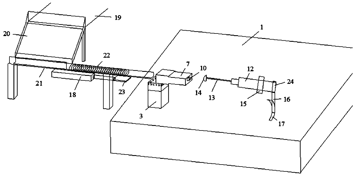
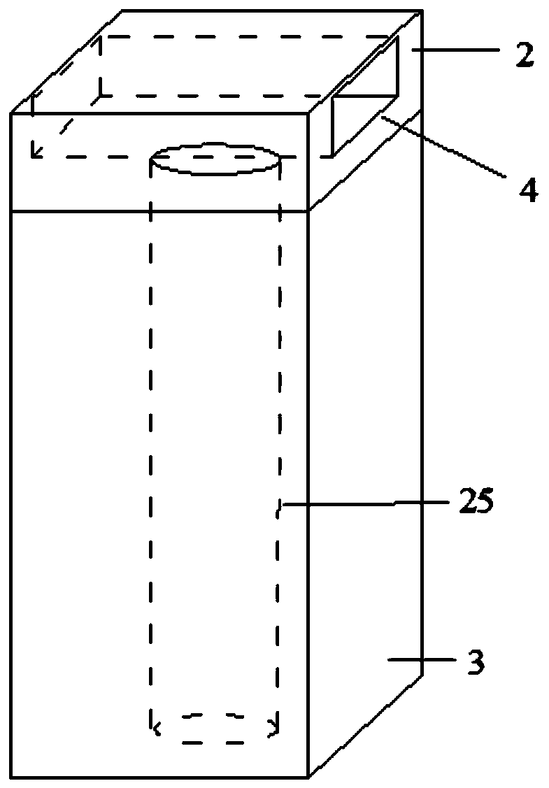
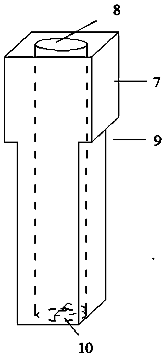
The invention discloses a hot stamping forming device for high-strength steel. The hot stamping forming device comprises a supporting table arranged horizontally, a supporting column in a square rod shape, a first motor, a rotating sleeve, a fixed cylinder, a first air cylinder and a second air cylinder, wherein the fixed cylinder is in a square pipe shape and is vertically arranged in the supporting table and located under the rotating sleeve, the second air cylinder is arranged on the left side of the supporting column, and the telescopic end of the second air cylinder can horizontally penetrate out of a square groove. When the rotating sleeve rotates around a pin shaft of a hinge to be in a horizontal state, a pushing plate can extend into and extend out of a second circular through hole from the position, except for a baffle, the hole bottom of the second circular through hole, and when the rotating sleeve rotates to be in a vertical state, the fixed cylinder extends out to clamp the lower portion of the rotating sleeve. The hot stamping forming device has the advantages of stable clamping and taking, high stamping efficiency and the like, and can be widely applied in the technical field of stamping equipment.

Description

technical field [0001] The invention relates to the technical field of hot stamping equipment. More specifically, the present invention relates to a hot stamping forming device for high strength steel. Background technique [0002] The hot stamping forming device for high-strength steel is used to heat the blank to a certain temperature, and then stamp the blank with a stamping die to obtain a molded part of the desired shape. [0003] The existing hot stamping forming device is time-consuming and cumbersome, after heating the billet, manually or with a robot to clamp the heated billet into the stamping die for stamping, which is time-consuming and troublesome, and the billet placed on the stamping table is unstable. The problem is that it is inconvenient to demould the molded parts after the stamping is completed, and manual or robotic hand is required for demoulding. This kind of hot stamping forming device is time-consuming and has low work efficiency. Contents of the ...

Claims


Application Information

Patent Timeline
Patent Type & Authority Patents(China)
IPC IPC(8): B21D22/02B21D43/10B21D45/04B21D37/16
CPCB21D22/022B21D37/16B21D43/10B21D45/04
Inventor 王韦雷涛贺东方陈志勇杨黄锐刘鹏龙曲波刘祥朱汉强王熠
Owner DONGFENG WUHAN IND
Learn More