Secondary buckling part molding angle-ejection device and injection mold

A technology of slanted top and slanted head, which is applied in the field of secondary buckle forming slanted top device and injection mold, which can solve the problems of lengthening the molding cycle, affecting the molding quality, and increasing the difficulty of design, so as to achieve the effect of ensuring smooth removal

Pending Publication Date: 2018-12-04
AUX AIR CONDITIONING LTD BY SHARE LTD
View PDF7 Cites 1 Cited by
  • Summary
  • Abstract
  • Description
  • Claims
  • Application Information

AI Technical Summary

Problems solved by technology

[0004] 1. There are many forming mechanisms, which increase the design difficulty, increase the processing cost, and indirectly lengthen the delivery time;
[0005] 2. The core-pulling molding rod is easy to rotate during the core-pulling process, which affects the molding quality;
[0006] 3. T

Method used


Image

  • Secondary buckling part molding angle-ejection device and injection mold
  • Secondary buckling part molding angle-ejection device and injection mold
  • Secondary buckling part molding angle-ejection device and injection mold

Examples


no. 1 example

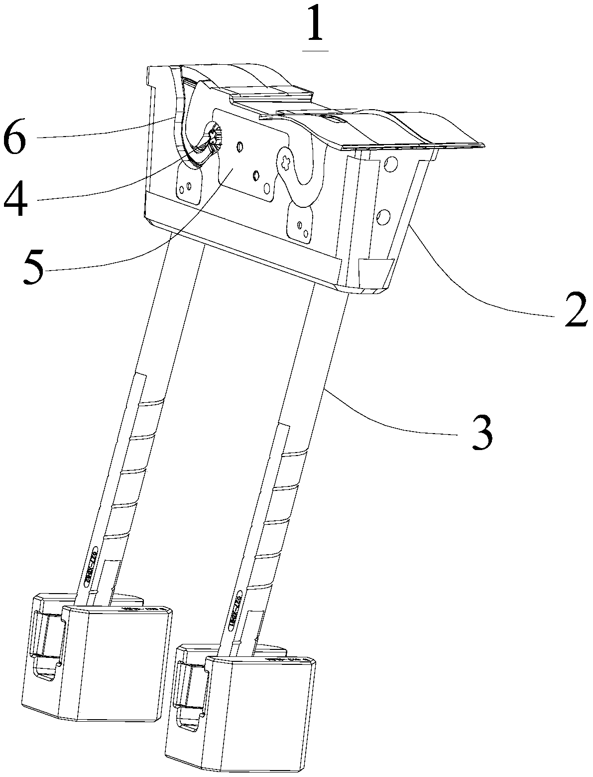
[0041] see in conjunction Figure 1 to Figure 3 , this embodiment provides a secondary buckle forming inclined top device 1, which is used to cooperate with the mold core to form the buckle structure and the buckle groove structure of the product.

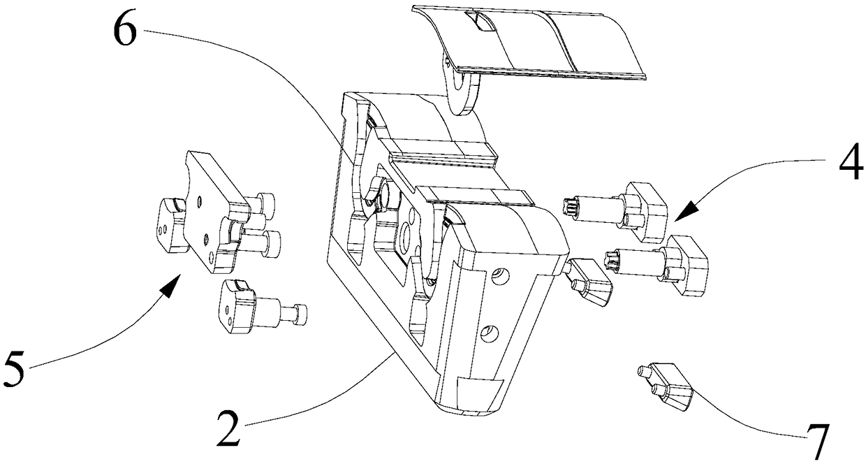
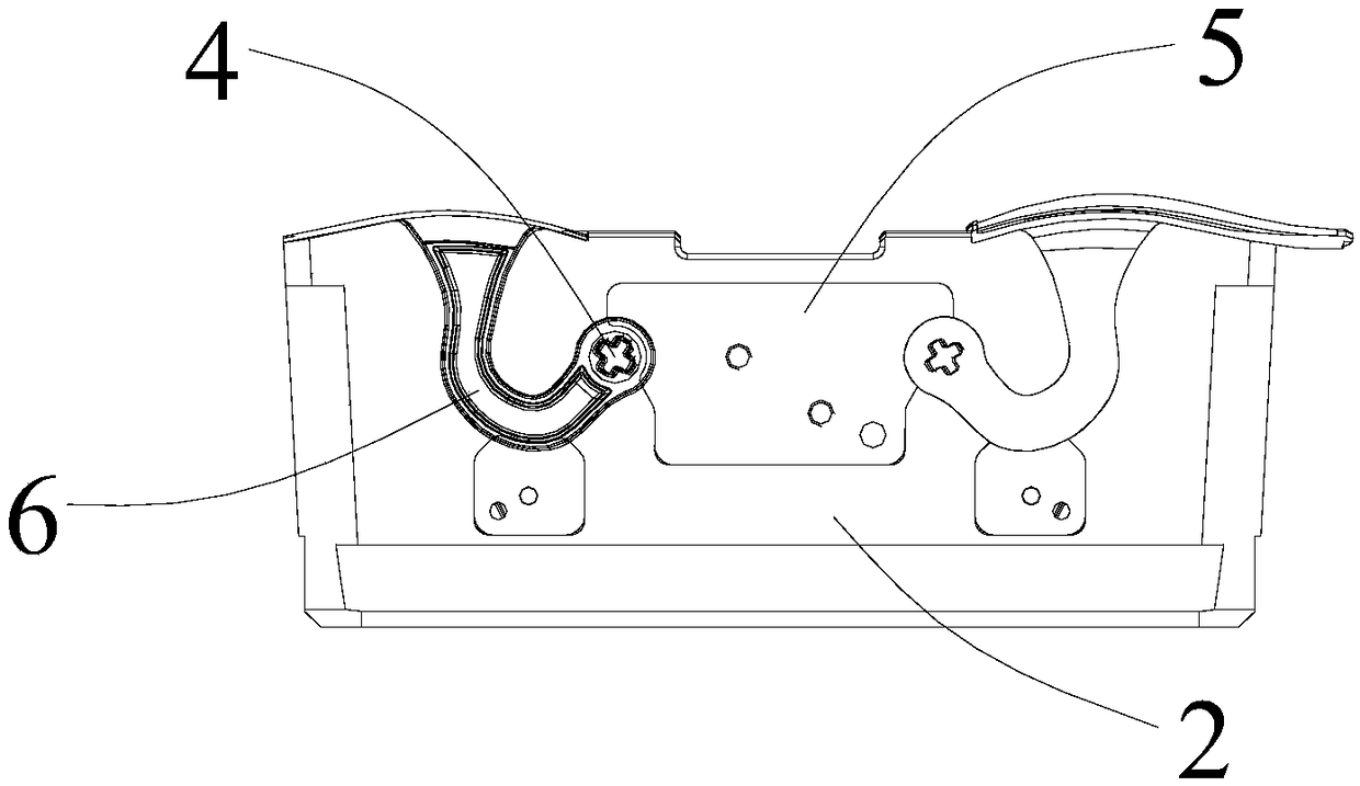
[0042]This secondary buckle forming inclined ejector device 1 comprises an inclined ejector head 2, an inclined ejector rod 3, a buckle forming insert 4 and a ejector block ejection assembly 5, the inclined ejector rod 3 is connected with the bottom of the inclined ejector head 2, and the inclined ejector head 2 has an opposite The front and back of the slanted head are provided with a molding groove 6 on the front of the slanted head, and the back of the slanted head 2 is provided with a needle jack, which runs through the slanted head 2 and communicates with the molding groove 6, and the buckle is formed with a 4 It is detachably arranged on the back of the slanting head 2 , and the end of the buckle molding insert 4 is inserted ...

no. 2 example

[0060] This embodiment provides an injection mold, which can form the buckle and the buckle groove at one time, which reduces the processing and material costs, and at the same time does not need to drive different mechanisms separately, shortens the injection molding cycle, and avoids the abnormal cooperation of different mechanism components situation arises. The injection mold includes a mold core and a secondary buckle forming inclined roof device 1, wherein the basic structure, principle and technical effect of the secondary buckle forming inclined roof device 1 are the same as those of the first embodiment. For a brief description, this embodiment For some parts not mentioned, reference may be made to the corresponding content in the first embodiment.

[0061] The secondary buckle forming inclined jacking device 1 includes an inclined jack 2, an inclined ejector rod 3, a buckle forming insert 4 and a ejector block ejection assembly 5, the inclined ejector rod 3 is connec...


PUM


Abstract

The invention provides a secondary buckling part molding angle-ejection device and an injection mold and relates to the technical field of injection molds. The secondary buckling part molding angle-ejection device comprises an angle ejection head, an angle ejection rod and a buckling part molding insert pin. The angle ejection rod is connected with the bottom of the angle ejection head. The frontof the angle ejection head is provided with a molding groove, and the back of the angle ejection head is provided with an insert pin jack, which penetrates through the angle ejection head and is communicated with the molding groove. The buckling part molding insert pin is detachably arranged at one side of the angle ejection head, far from the molding groove. An end portion of the buckling part molding insert pin is inserted into the insert pin jack from the back of the angle ejection head and extends into the molding groove. According to the secondary buckling part molding angle-ejection device, through the integrated structure, the buckling part and the buckling groove can be molded at a time, thereby reducing processing and material costs. Meanwhile, there is no need to separately drivedifferent molding mechanisms, the injection moulding period is shortened, and abnormity of combining different mechanical parts is avoided.

Description

technical field [0001] The invention relates to the technical field of injection molds, in particular to a secondary buckle forming inclined roof device and an injection mold. Background technique [0002] In the process of traditional injection molding, when it is necessary to form buckles and buckle grooves on the product, it is necessary to use two mechanisms, the inclined top mechanism and the slider mechanism, in which the slider mechanism is provided with holes for forming the buckle grooves The core-pulling forming rod, and the core-pulling forming rod needs to cooperate with the inclined top mechanism. During the forming process, the slider mechanism and the inclined top mechanism need to be driven separately to form the buckle groove and the buckle position respectively. [0003] When using the above forming system to form the buckle and buckle groove of the product, it has the following disadvantages: [0004] 1. There are many forming mechanisms, which increase t...

Claims


Application Information

Patent Timeline
IPC IPC(8): B29C45/44
CPCB29C45/4435
Inventor 魏年森禹琰谭仕建
Owner AUX AIR CONDITIONING LTD BY SHARE LTD
Why Eureka
Try Eureka