
Transport device for web winder

A technology of fiber web and winding machine, which is applied in the direction of winding mechanism, fiber processing, winding strip, etc. It can solve the problems of falling off and winding shaft detachment, and achieve the effect of improving safety

Active Publication Date: 2018-12-04
特吕茨施勒集团欧洲公司
View PDF11 Cites 2 Cited by
  • Summary
  • Abstract
  • Description
  • Claims
  • Application Information

AI Technical Summary

Problems solved by technology

Especially for the operator, this is a very dangerous situation, because the winding shaft may detach and fall

Method used


Image

  • Transport device for web winder
  • Transport device for web winder
  • Transport device for web winder

Examples


Embodiment Construction

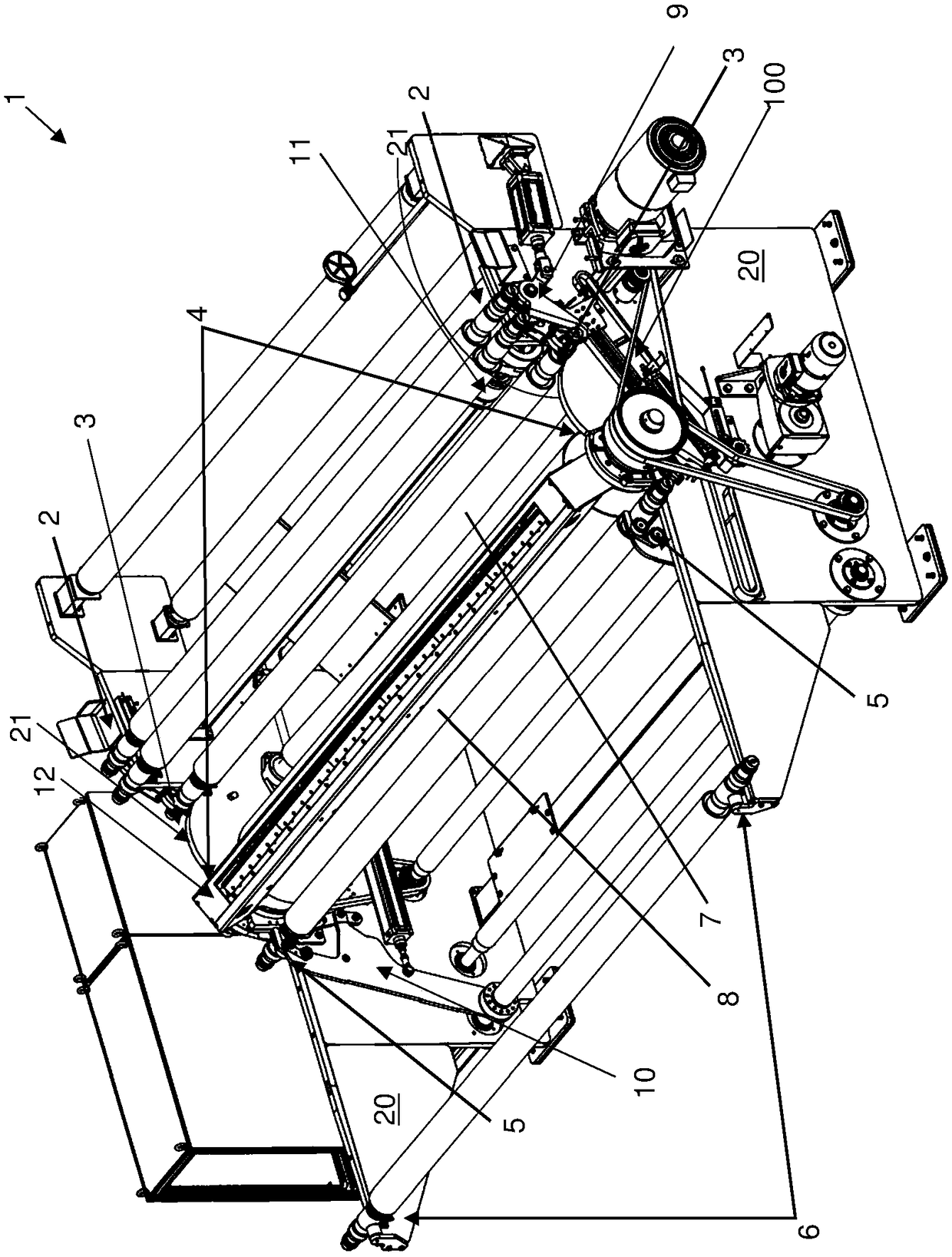
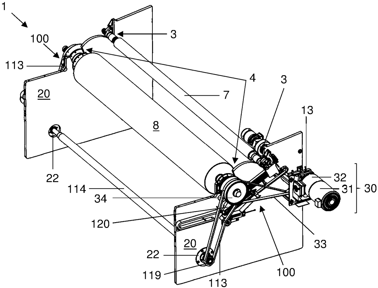
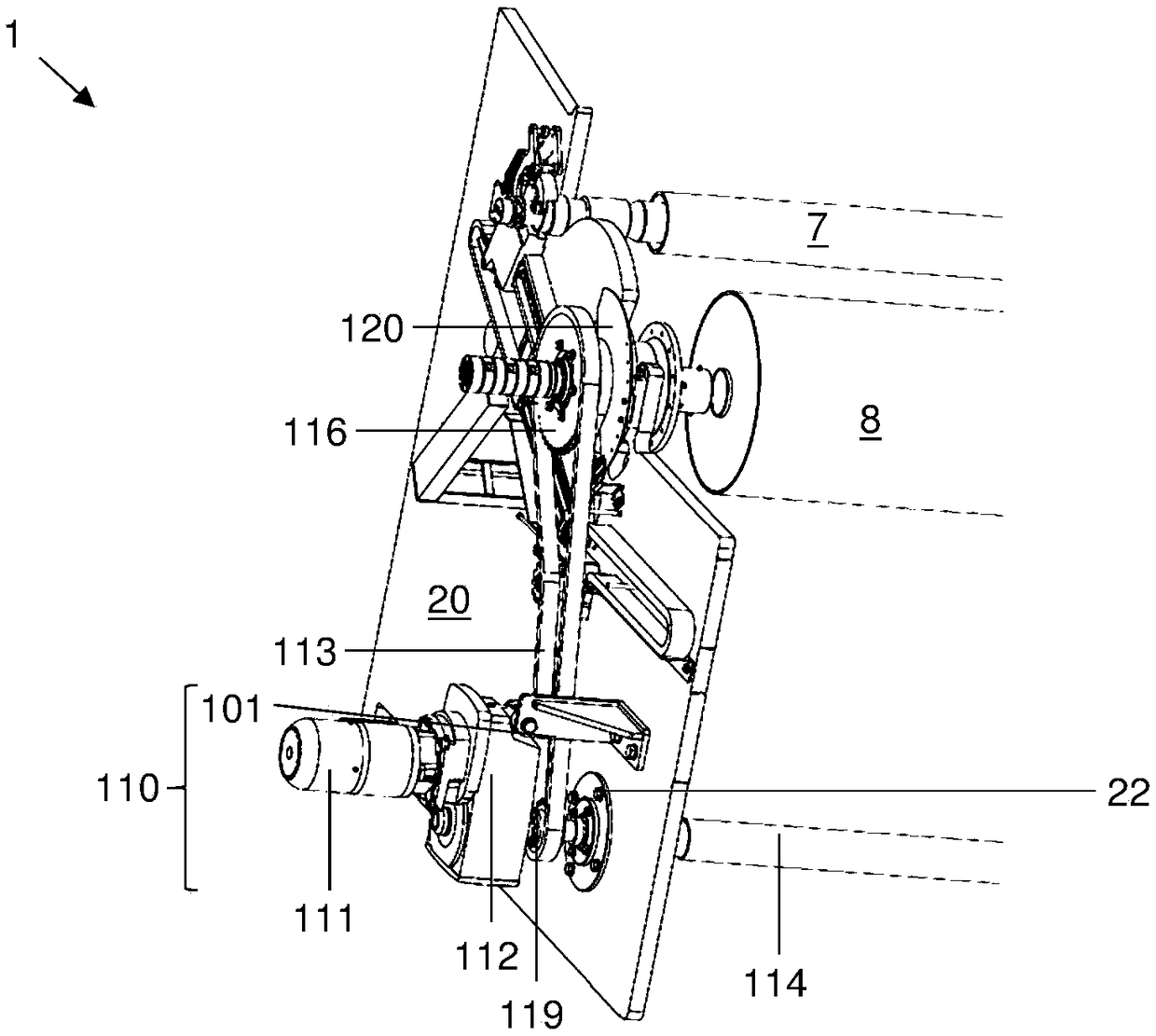
[0027] figure 1 A web winding machine 1 according to an embodiment of the invention is shown. Components that are not essential to the present invention will not be explained in detail.

[0028] The web winding machine 1 essentially comprises two frame walls 20 , which form, via unmarked connections, a frame which accommodates or holds all other functional components of the web winding machine 1 .

[0029] In the area on the right, the machine frame wall 20 has a depository 2 in which unmarked winding shafts (here: two) are located.

[0030] The web winder 1 also comprises a recess on each frame wall 20 defining a waiting position 3 for the winding shaft 7 . Since the winding shaft is held on both sides by the frame walls 20 , the waiting position 3 is realized with two frame walls 20 . The machine frame wall 20 thus forms, with the waiting position 3 , a holding section for the winding shaft 7 to be wound.

[0031] In the waiting position 3 , the winding shaft 7 arranged ...


PUM


Abstract

A web winder (1) has a holding section (3), a transport section (100) and a guiding section (20). The holding section (3) is configured to receive a winding shaft (7). The guide section (20) has a moving surface (21) substantially away from the ground of the erect web winder (1) and is configured to bear the weight of the winding shaft (7). The transport section (100) and the guiding section (20)are configured to move the winding shaft (7) from the holding section (3) toward a winding-starting position (4) on or near the moving surface (21). In the winding-starting position, the web winder (1) sets up so as to start winding a web on a contact roll (8) of the web winder (1) by the winding shaft (7). The invention also relates to a method for operating a web winder (1).

Description

technical field [0001] The invention relates to a device for transporting a winding shaft in a web winding machine from a waiting position of the web winding machine to an unwinding position and from an unwinding position to a winding position and a device equipped with such a The fiber web winding machine of the device. Background technique [0002] Fiber web winders are known per se. These web winders are used to wind a web, for example from a card, onto a winding shaft. For this purpose, the empty winding shaft is placed in the storage and gradually brought first to the waiting position. The waiting position serves on the one hand to separate the winding shaft from the other winding shafts and on the other hand to allow the winding shaft to rotate before starting the actual winding process. In order to start winding the winding shaft it is stipulated that the winding shaft is transported from the waiting position to the starting position, in which the winding shaft to ...

Claims


Application Information

Patent Timeline
IPC IPC(8): B65H19/30
CPCB65H19/30B65H19/305D01G27/00B65H18/028B65H18/16B65H2301/41822B65H2701/174
Inventor 克吕斯托夫·巴尔洛克安德烈亚斯·哈赫曼
Owner 特吕茨施勒集团欧洲公司
Learn More