Construction method facilitating guarantee of hollow floor structural size

A technology of structural size and construction method, applied in building structure, processing of building materials, construction, etc., can solve problems such as large deviation between structural size and design, occupancy box or steel bar tilting, affecting building manufacturing quality, etc. Achieve the effects of improving manufacturing quality, increasing material costs, and making connection and construction operations simple and convenient

CN108930409AInactive Publication Date: 2018-12-04CHINA METALLURGICAL CONSTR ENG GRP
5 Cites 3 Cited by

Patent Information

Authority / Receiving Office
CN · China
Patent Type
Applications(China)
Current Assignee / Owner
Publication Date
2018-12-04
Estimated Expiration
Not applicable · inactive patent

Smart Images

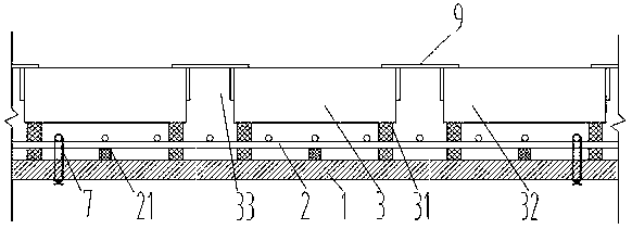
  • Figure 1
    Figure 1
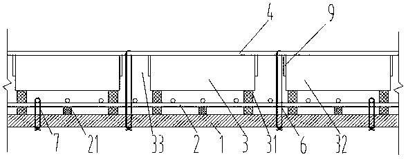
  • Figure 2
    Figure 2
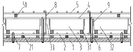
  • Figure 3
    Figure 3
Patent Text Reader

Abstract

The invention relates to a construction method facilitating guarantee of hollow floor structural size. The construction method comprises the following steps that S1, a horizontal bottom formwork is laid; S2, a plurality of bottom layer steel bar cushion blocks are arranged on the bottom formwork, and a bottom steel bar layer is laid; S3, a plurality of second connecting pieces are used for connecting the bottom steel bar layer with the bottom formwork; S4, a plurality of placeholder box body cushion blocks are arranged on the bottom formwork, and a placeholder box body layer is laid; S5, an anti-floating steel bar layer is laid on the placeholder box body layer, and the anti-floating steel bar layer is supported by the placeholder box body layer; S6, a plurality of first connecting piecesare used for connecting anti-floating layer and the bottom formwork; S7, a plurality of top layer steel rib cushion blocks are arranged on the placeholder box body layer, and a top steel bar layer islaid; and S8, a plurality of third connecting pieces are used for connecting the top steel bar layer and the bottom steel bar layer. The anti-floating steel bar layer and the first connecting pieces are used for preventing placeholder box body tilting float after concrete slurry pouring, components in the floor are effectively fixed to guarantee the structure size of the floor to meet design sizerequirements and improve floor quality.
Need to check novelty before this filing date? Find Prior Art

Description

technical field

[0001] The invention belongs to the technical field of general building structures in buildings, and in particular relates to a construction method which is beneficial to ensure the structural size of hollow floor slabs. Background technique

[0002] For frame structure buildings, the commonly used cast-in-place concrete slabs are ordinary solid slabs or ribbed solid slabs. After the force analysis, the floor is a load-bearing member, which undergoes slight bending deformation when it is stressed. The upper layer is a compression area, which bears pressure, and the lower layer is a tension area, which bears tension. In order to reduce the weight of the floor and save the amount of concrete, the middle layer of the floor can be reduced. Concrete, forming the upper and lower reinforced concrete layers and the structural form of reinforced concrete dense ribs required to connect the upper and lower layers so that they can bear the force and resist shear. The red...

Examples

Embodiment Construction

[0049] The specific implementation manners of the present invention will be further described in detail below in conjunction with the accompanying drawings.

[0050] see Figure 1-5 , the specific embodiment of the present invention is beneficial to the construction method that guarantees the structural size of the hollow floor slab, comprising the following steps:

[0051] S1, laying horizontal bottom formwork 1 and side forms (not shown in the figure);

[0052] S2, place some bottom reinforcement pads 21 on the bottom template 1 according to the design position, and then lay the bottom reinforcement layer 2; the bottom reinforcement layer 2 is jointly supported by all bottom reinforcement pads 21;

[0053] S3. Use several second connectors 7 to connect the bottom reinforcing bar layer 2 with the bottom template 1 to limit the upward movement of the bottom reinforcing bar layer 2; see figure 1 ;

[0054] S4. Place a number of occupancy box pads 31 on the bottom template 1 ...