Intake duct for internal combustion engine

A technology for intake pipes and internal combustion engines, which is applied in the field of intake pipes and can solve problems such as increased airflow resistance

Inactive Publication Date: 2018-12-04
TOYOTA BOSHOKU KK
View PDF5 Cites 3 Cited by
  • Summary
  • Abstract
  • Description
  • Claims
  • Application Information

AI Technical Summary

Problems solved by technology

Therefore, the airflow resistance of the main flow of incoming air flowing through the intake pipe increases

Method used


Image

  • Intake duct for internal combustion engine
  • Intake duct for internal combustion engine
  • Intake duct for internal combustion engine

Examples


Embodiment Construction

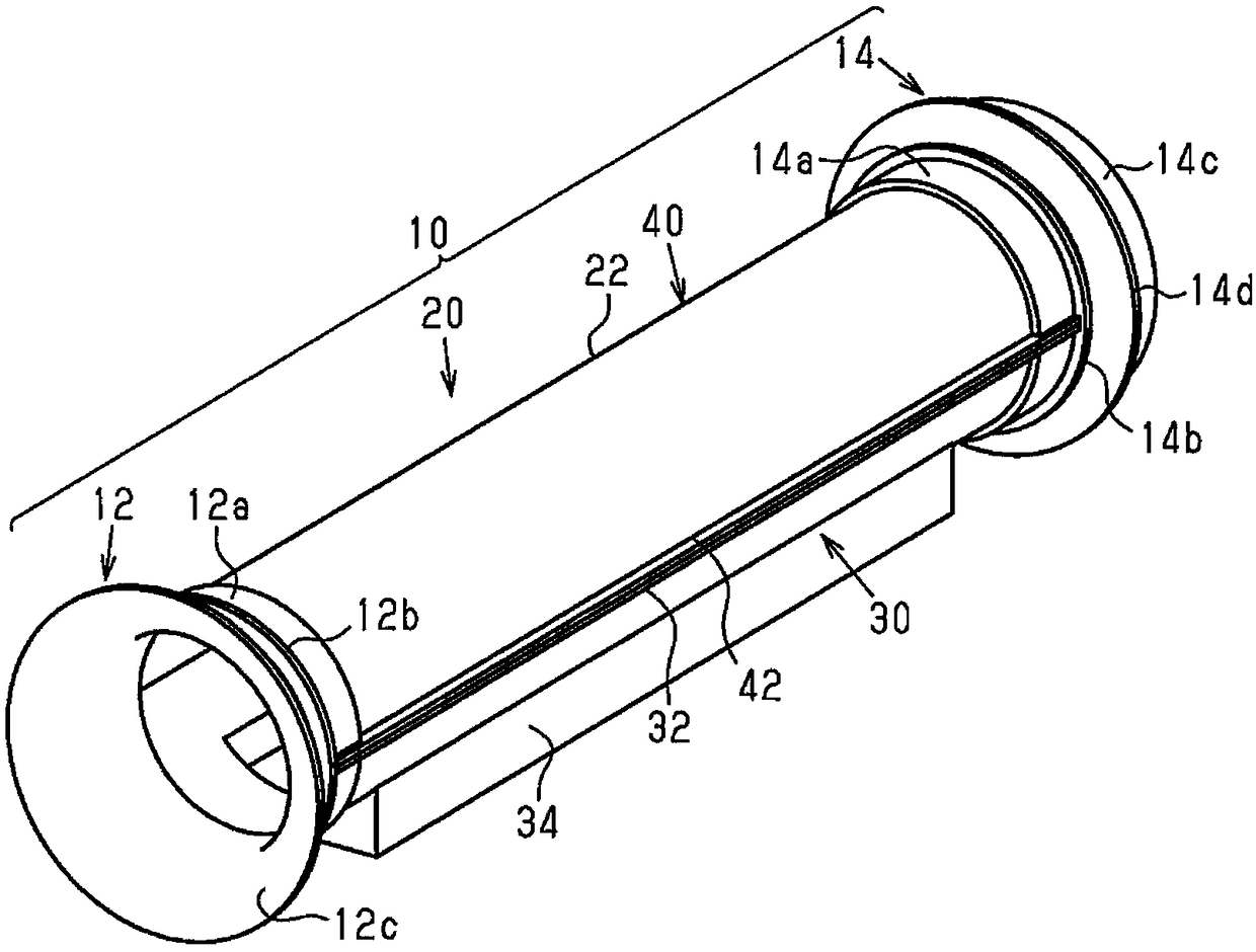
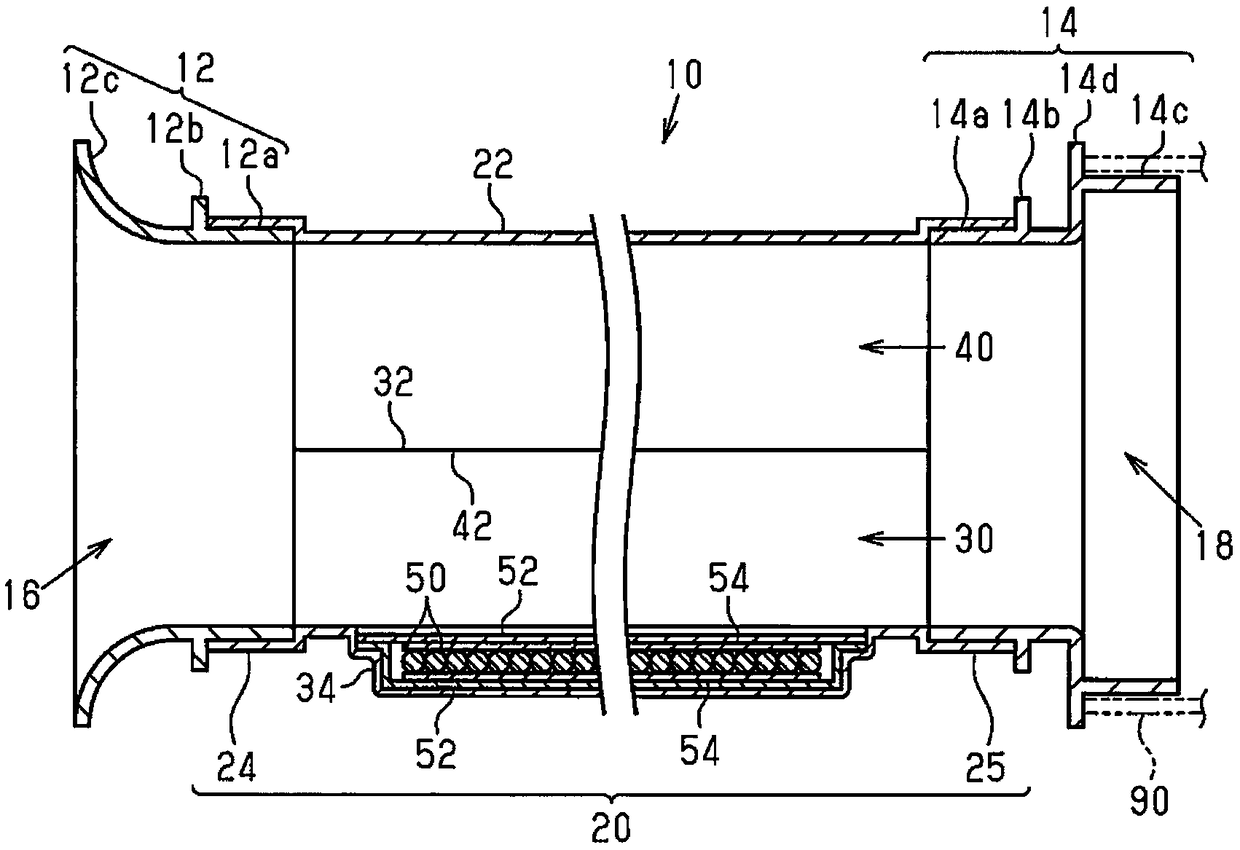
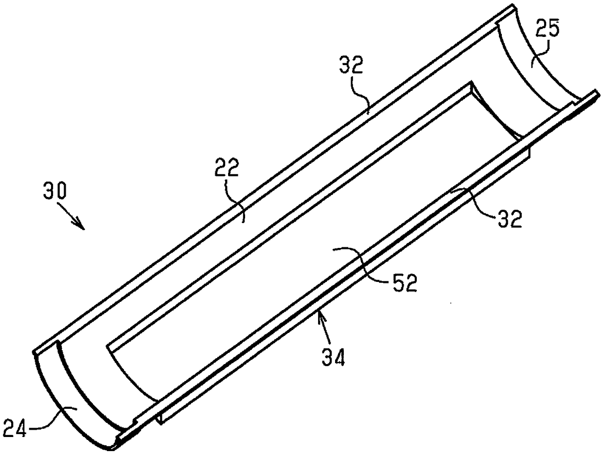
[0012] will now refer to Figure 1 to Figure 5 One embodiment will be described.

[0013] Such as figure 1 and figure 2 As shown, an intake pipe 10 for an internal combustion engine includes an upstream side connecting member 12 , a pipe main body 20 and a downstream side connecting member 14 . The intake pipe 10 is connected to the figure 2 The double-dashed line in represents the air intake 90 of the air filter and constitutes a part of the intake passage.

[0014] In the following description, the upstream side and the downstream side in the flow direction of the incoming air in the intake pipe 10 are simply referred to as the upstream side and the downstream side, respectively.

[0015]

[0016] Such as figure 1 and figure 2 As shown, the upstream connection member 12 is made of hard plastic, has a cylindrical shape, and constitutes an inlet 16 of the intake pipe 10 . The upstream connection member 12 includes a cylindrical connection portion 12a, an annular pr...


PUM

PropertyMeasurementUnit
Weightaaaaaaaaaa

Abstract

An intake duct for an internal combustion engine includes a cylindrical duct main body. The duct main body includes an inner layer and an air-impermeable sheet. The inner layer is made of an air-permeable first fiber molding and constitutes the inner circumferential surface of the duct main body. The air-impermeable sheet is fixed to the outer circumferential surface of the inner layer. The weightper unit area of the sheet is 15 to 100 g / m2.

Description

technical field [0001] The invention relates to an intake pipe for an internal combustion engine. Background technique [0002] Japanese Patent Laid-Open No. 11-343939 discloses an intake pipe for an internal combustion engine formed by a compression-molded body of nonwoven fabric containing a thermoplastic resin binder. The intake pipe of this publication has a hard portion with a high compression ratio and a soft portion with a low compression ratio. In the intake pipe of this publication, at least part of the wall is formed of a soft portion having air permeability to a certain extent. Therefore, some sound waves of the incoming air pass through the soft part. This suppresses generation of standing waves of sound waves of incoming air, thereby reducing intake noise. [0003] External air is introduced into the intake duct of the publication by negative pressure in the intake duct of the internal combustion engine. This increases the thickness of the boundary layer for...

Claims


Application Information

Patent Timeline
IPC IPC(8): F02M35/104B32B27/36B32B27/34B32B27/32B32B27/06B32B27/08B32B27/02B32B7/10B32B1/08
CPCB32B1/08B32B5/02B32B5/26B32B7/10B32B2262/0253B32B2262/0261B32B2262/0284B32B2307/7242B32B2597/00F02M35/10334F02M35/104B32B5/022B32B5/08B32B7/12B32B27/12B32B27/34B32B2250/03B32B2250/04B32B2250/40B32B2262/12B32B2307/102B32B2307/306B32B2307/724B32B2307/732F02M35/10098B32B2037/1223
Inventor 木村龙介
Owner TOYOTA BOSHOKU KK
Why Eureka
Try Eureka