Terminal handling device

A loading and unloading device and terminal technology, which is applied in the direction of electrical components, connections, and electrical component connections, can solve problems such as cumbersome operations

Active Publication Date: 2021-05-11
HIROSE ELECTRIC GROUP
View PDF5 Cites 0 Cited by
  • Summary
  • Abstract
  • Description
  • Claims
  • Application Information

AI Technical Summary

Problems solved by technology

[0004] In the existing terminal attachment and detachment device, in order to connect the terminal 117 or in order to pull out the terminal 117, it is necessary to pull up the operation of the handle part 111, and the operation is cumbersome.

Method used


Image

  • Terminal handling device
  • Terminal handling device
  • Terminal handling device

Examples


Embodiment Construction

[0047] Hereinafter, a terminal attachment and detachment device according to a preferred embodiment of the present invention will be described with reference to the drawings. As an example, an application example of the present invention is described in a device having a terminal switching function, that is, a device capable of electrically switching at least two terminals, but this is only an application example, and is not intended to limit the present invention to a device with a terminal switching function. Device for terminal transfer function. The present invention can be widely applied to terminal loading and unloading devices that do not have such a terminal transfer function.

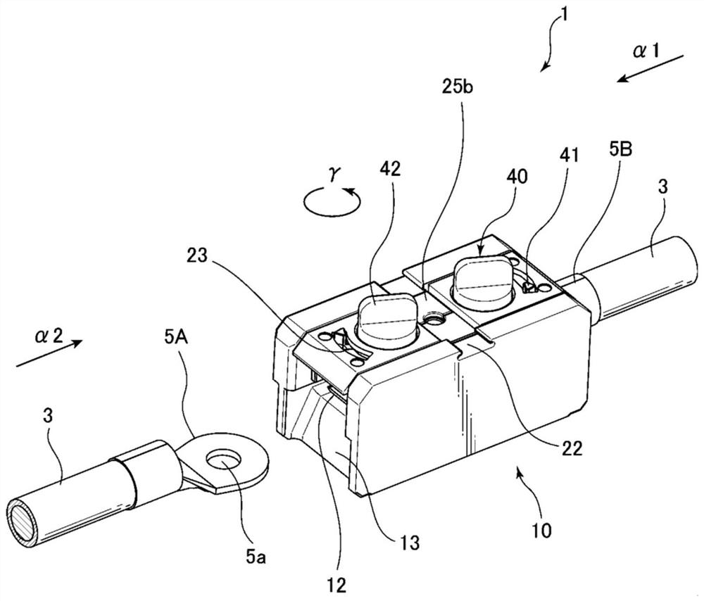
[0048] figure 1 It is a perspective view showing an example of the use mode of the terminal attaching and detaching device 1 to which the present invention can be applied, figure 2 It is a top view showing how the device 1 is used. The terminal attachment and detachment device 1 does not n...


PUM


Abstract

An object of the present invention is to improve the operability of a terminal attaching and detaching device. This terminal attachment and detachment device includes: a housing; an engaging member that moves in a first direction toward a terminal disposed at a predetermined position of the housing to engage with the terminal, and moves in a second direction from the terminal disposed at the predetermined position to release engagement with the terminal; and an operation member provided rotatably with respect to the case. The engaging member can rotate relative to the housing according to the rotation of the operating member, and can move in the first direction or the second direction relative to the housing according to the rotation relative to the housing.

Description

technical field [0001] The present invention relates to a terminal loading and unloading device. Background technique [0002] For example, terminal attachment and detachment devices are used for attaching and detaching terminals to switchboards, machine tools, and computer products. In particular, Patent Document 1 shows an example of a terminal attaching and detaching device provided with a terminal switching function. According to this terminal attaching and detaching device, the terminal can be attached or detached by a simple operation without using screws. [0003] Figure 19 A configuration example of the terminal attaching and detaching device disclosed in Patent Document 1 is shown. In order to connect the terminals 117 to each other, the knob part 111 is pulled up against the force of the coil spring 115, and in this state, the terminal 117 is inserted between the pressure plate 114 of the base body 107 and the connection fitting 108, and then the knob part 111 i...

Claims


Application Information

Patent Timeline
Patent Type & Authority Patents(China)
IPC IPC(8): H01R4/48H01R11/09H01R11/01
CPCH01R4/4872H01R11/01H01R11/09H01R4/48365H01R4/366H01R4/54H01R11/12H01R9/20
Inventor 田中洋则
Owner HIROSE ELECTRIC GROUP
Why Eureka
Try Eureka