Manual leather shoe eyelet riveting device

A shoe eye, manual technology, applied in the direction of footwear, clothing, fasteners, etc., can solve the problem of taking a long time, and achieve the effect of less time-consuming and high-efficiency installation

Inactive Publication Date: 2018-12-07
DONGGUAN LIANZHOU INTPROP OPERATION MANAGEMENT CO LTD
View PDF0 Cites 2 Cited by
  • Summary
  • Abstract
  • Description
  • Claims
  • Application Information

AI Technical Summary

Problems solved by technology

The shoe eyelets are generally fixed on the upper by riveting. In the existing manual shoemaking, tools such as hammers are used to hit the shoe eyelets to achieve riveting pressure. This kind of knocking method takes a long time to install the shoe eyelets.

Method used


Image

  • Manual leather shoe eyelet riveting device
  • Manual leather shoe eyelet riveting device
  • Manual leather shoe eyelet riveting device

Examples


Embodiment

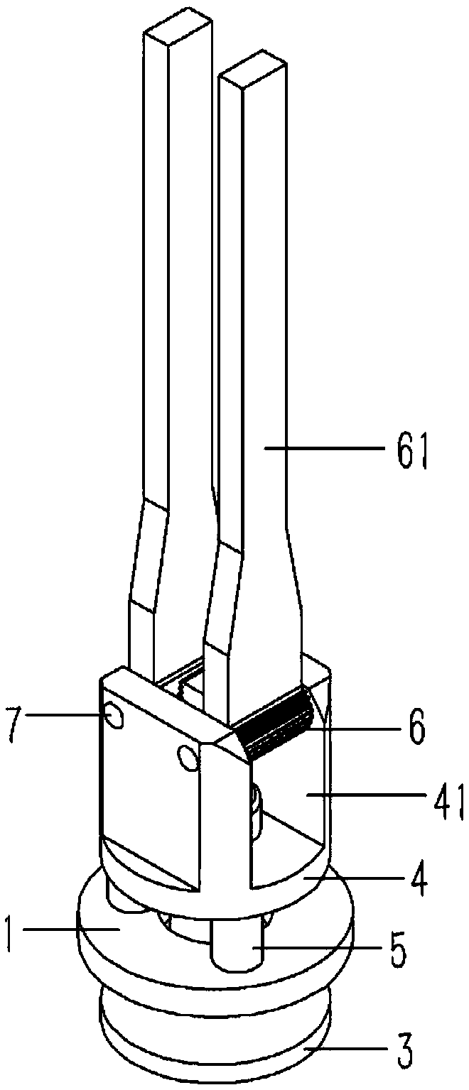
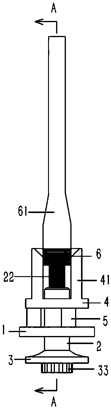
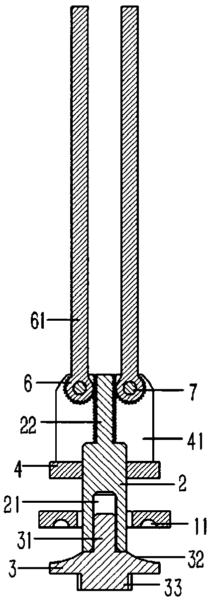
[0016] Example: see Figures 1 to 3 As shown, a manual riveting device for shoe eyelets of leather shoes includes an upper platen 1 and a lower platen 3, the upper platen 1 is formed with a center hole, and a vertical positioning pin is inserted into the center hole of the upper platen 1. Column 2, the lower end of the positioning column 2 exposes the lower end surface of the upper platen 1 and is formed with a bottom threaded hole 21; A stud 31 is formed, and the stud 31 is screwed in the bottom threaded hole 21 of the positioning column 2; The two ends of 5 are respectively fixed on the upper pressure plate 1 and the positioning plate 4, the upper end of the positioning column 2 passes through the positioning plate 4 to form a rack 22, and both sides of the rack 22 are formed with tooth grooves, the rack 22 A gear 6 is meshed in the tooth grooves on both sides, and a riveting handle 61 is formed on the gear 6; a vertical side plate 41 is formed on the upper surface of the p...


PUM


Abstract

The invention discloses a manual leather shoe eyelet riveting device which comprises an upper compressing plate and a lower compressing plate. A vertical positioning column is plug-connected into a central hole of the upper compressing plate, the lower end of the positioning column is exposed out of the lower end face of the upper compressing plate and is provided with a bottom threaded hole. Theside wall of the lower compressing plate is provided with a circular-arc-shaped concave surface, the upper end face of the lower compressing plate is provided with a stud, and the stud is screwed in the bottom threaded hole of the positioning column. The upper end of the positioning column is plug-connected to a positioning plate, the positioning column is peripherally provided with a plurality ofconnecting columns, two ends of the each connecting column are respectively fixed to the upper compressing plate and the positioning plate, the upper ends of the positioning columns penetrate throughthe positioning plate to be provided with a rack, two side end faces of the rack are both provided with tooth grooves, the tooth grooves formed in two sides of the rack are meshed with gears, and riveting handles are formed on the gears. Vertical side plates are formed on the upper end faces of the portions, on two sides of the rack, of the positioning plate, and the gears are plug-connected between the side plates of the positioning plate and hinged to the side plates through articulated shafts. The manual leather shoe eyelet riveting device facilitates achievement of leather shoe eyelet riveting, the time consumed for shoe eyelet installation is short, and the efficiency is high.

Description

Technical field: [0001] The invention relates to the technical field of shoemaking machinery, in particular to a manual riveting device for leather shoe eyelets. Background technique: [0002] Shoes are the necessities of wearing in people's daily life. Some shoes need to be equipped with shoe ropes for lacing, so that the upper of the shoes is required to have rope holes; after the upper is perforated, the rope holes need to be protected. Generally, metal eyelets are installed on the rope holes to avoid rope holes Stretched by shoestrings. The shoe eyelets are generally fixed on the upper by riveting. In the existing manual shoemaking, tools such as hammers are used to knock the shoe eyelets to achieve riveting pressure. This kind of knocking method requires a long time for shoe eyelet installation. Invention content: [0003] The object of the present invention is to provide a manual riveting device for eyelets of leather shoes in view of the deficiencies of the prior ...

Claims


Application Information

Patent Timeline
Patent Type & Authority Applications(China)
IPC IPC(8): A43D100/02
CPCA43D100/02
Inventor 徐亚维
Owner DONGGUAN LIANZHOU INTPROP OPERATION MANAGEMENT CO LTD
Why Eureka
Try Eureka