
Interlocking components and cooking appliances

A cooking utensil and interlocking technology, which is applied in the field of cooking utensils with the above-mentioned interlocking components, can solve the problems of high closing force, paint peeling on the door body, violent collision of the door body, etc.

Active Publication Date: 2019-03-15
GUANGDONG MIDEA KITCHEN APPLIANCES MFG CO LTD +1
View PDF8 Cites 0 Cited by
  • Summary
  • Abstract
  • Description
  • Claims
  • Application Information

AI Technical Summary

Problems solved by technology

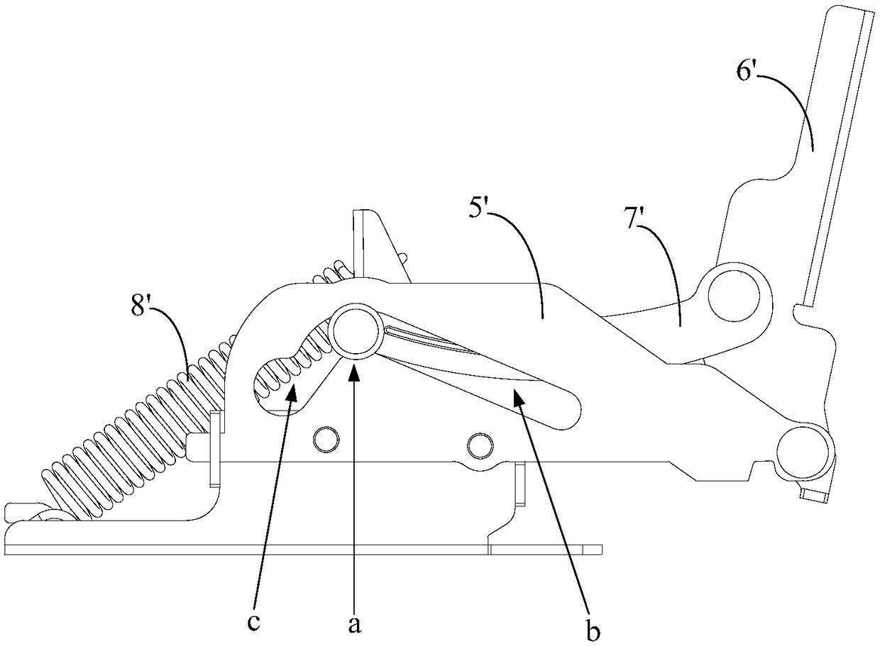
When the opening angle of the door body is greater than a certain preset value, the slider exceeds the hover critical point a and enters the section b of the V-shaped chute. At this time, the tension of the spring 8' is less than the weight of the door body, and the door body can hover; When the opening angle of the body is less than the preset value, the slider is located in the c-section of the V-shaped chute, the tension of the spring 8' is far greater than the weight of the door body, and the door enters the stage of automatic closing, and the tension of the spring 8' makes the door generate An angular acceleration makes the door continuously accelerate, and finally accumulates a large momentum at the moment before it is fully attached to the front panel of the cabinet, resulting in the same effect as the user closing the door too hard, making the door violently hit the front of the cabinet plate, causing the paint on the front panel or door of the cabinet to fall off

Method used


Image

  • Interlocking components and cooking appliances
  • Interlocking components and cooking appliances
  • Interlocking components and cooking appliances

Examples


Embodiment 1

[0045] Such as Figure 4 to Figure 7 As shown, the interlocking assembly provided by this solution includes a door hook 1, an interlocking bracket 2, an interlocking rotary block 3, a positioning torsion spring 4 and a buffer torsion spring 5. The door hook 1 is arranged on the surface of the door body facing the box. And the door hook 1 is provided with a limit hole 11; the interlocking bracket 2 is fixedly installed on the box body, and the interlocking bracket 2 is provided with a mounting column 21; 21 rotation, the interlocking rotary block 3 is provided with a limit protrusion 31 for cooperating with the limit hole 11; one end of the positioning torsion spring 4 is rotationally connected with the interlocking bracket 2, and the other end is rotationally connected with the interlocking rotary block 3; One end of the torsion spring 5 interferes with the interlock bracket 2 , and the other end is used for interference with the interlock rotary block 3 .

[0046] The workin...

Embodiment 2

[0055] The interlocking components provided by this solution include door hooks, interlocking brackets, interlocking rotary blocks, positioning torsion springs and buffer springs. The lock bracket is fixedly installed on the box body, and the interlock bracket is provided with a mounting column; the interlock rotating block is set on the mounting column and can rotate relative to the mounting column, and the interlock rotating block is provided with a limit hole for matching with the limit hole. One end of the positioning torsion spring is rotatably connected with the interlock bracket, and the other end is rotatably connected with the interlock rotary block; the buffer device includes a buffer spring, one end of the buffer spring is matched with the interlock bracket, and the other end is used for interlock with the interlock rotary block Cooperate.

[0056] In this solution, the buffering torsion spring in the first embodiment is replaced by a buffering spring, and the linka...


PUM


Abstract

The invention provides an interlocking assembly and a cooking utensil. The interlocking assembly comprises a door hook, an interlocking support, an interlocking rotary block, a positioning torsional spring and a buffer device. According to the scheme, the buffer device is additionally arranged on the basis of an existing interlocking assembly, a door body is in an open state, the interlocking rotary block is in an unlocking position, and the door hook and the interlocking rotary block are separated; and in the door closing process, the door hook abuts against the interlocking rotary block and then pushes the interlocking rotary block to rotate, the buffer device applies resistance to the interlocking rotary block in the process that the interlocking rotary block rotates to a locking position from the unlocking position, momentum of the door body is reduced so that impact to a box body front plate can be reduced when the door body is closed, and thus the problem that paint of the box body front plate or the door body is peeled off due to the fact that door closing force of a user or a tension hinge is too large is solved.

Description

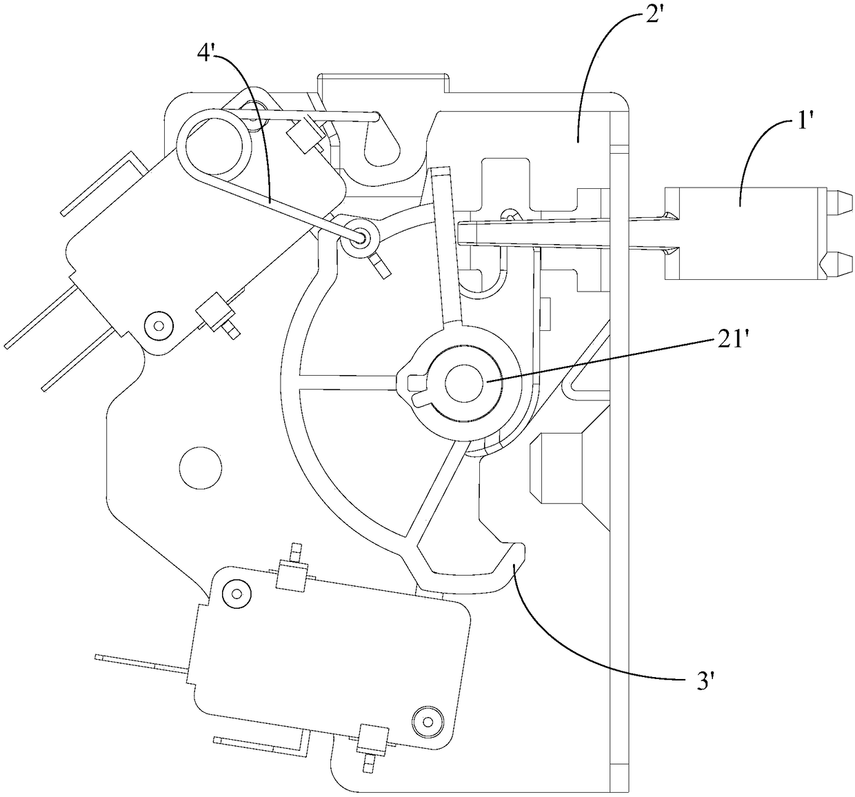
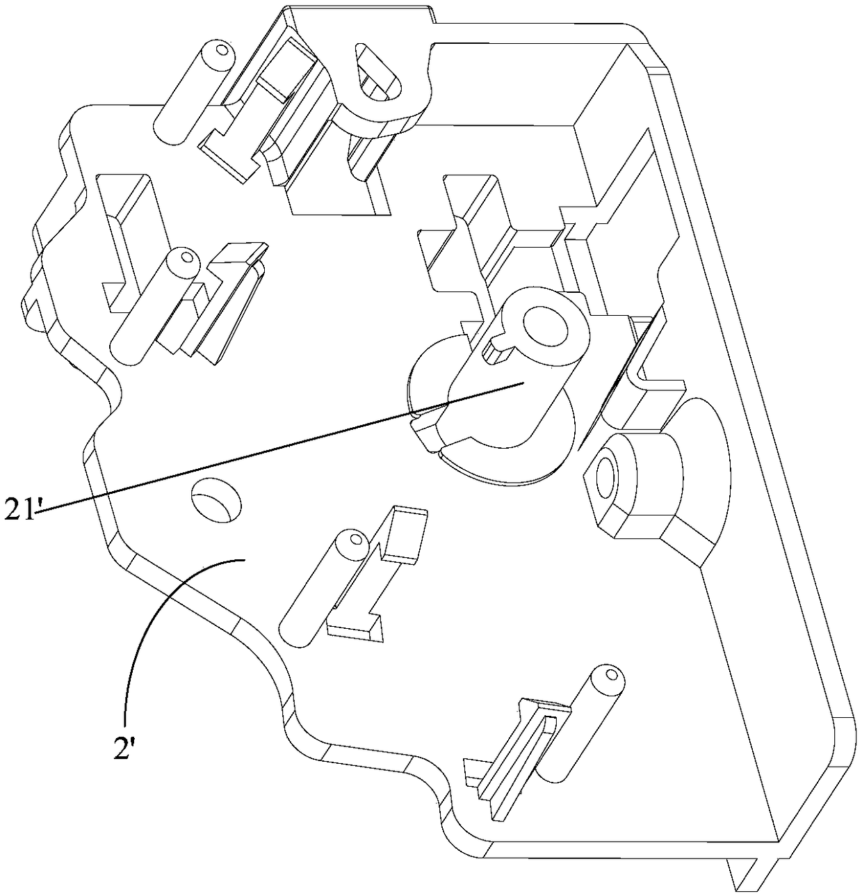
technical field [0001] The present invention relates to the field of cooking utensils, and more specifically, to an interlocking assembly and a cooking utensil having the above interlocking assembly. Background technique [0002] At present, some cooking utensils include hinged doors and cabinets, such as microwave ovens, electric ovens and other products. These products are usually equipped with interlocking components, such as figure 1 and figure 2 As shown, the interlocking assembly mainly includes a door hook 1', an interlocking bracket 2', an interlocking rotary block 3' and a positioning torsion spring 4'. The door hook 1' is arranged on the surface of the door body facing the box, and the door hook There is a limit hole on 1'; the interlocking bracket 2' is fixedly installed on the box body, and the interlocking bracket 2' is provided with a mounting column 21'; the interlocking rotary block 3' is set on the mounting column 21' and can be relatively The installatio...

Claims


Application Information

Patent Timeline
Patent Type & Authority Patents(China)
IPC IPC(8): E05B65/52A47J37/06
CPCA47J37/06E05B65/52
Inventor 杨伦周宏何衍文
Owner GUANGDONG MIDEA KITCHEN APPLIANCES MFG CO LTD
Learn More