
Torque-limiting screwdrivers

a screwdriver and torque limit technology, applied in the field of torque limiters, can solve the problems of reducing the safety of the screw and the plate, reducing the rotational speed of the screw, and increasing the amount of time available for sensing operations

Active Publication Date: 2016-02-23
PRO DEX INC
View PDF165 Cites 25 Cited by
  • Summary
  • Abstract
  • Description
  • Claims
  • Application Information

AI Technical Summary

Benefits of technology

[0006]It can be beneficial to avoid, or at least inhibit, stripping of the surgical screw in the bone. This can be accomplished with a screwdriver that monitors the torque applied to the screw and stops or reduces the rotation of the screw when certain torque criteria are satisfied. For example, the criteria can include the amount of torque being applied, how the torque is changing over time (e.g., whether the torque is consistently or inconsistently increasing or decreasing), and whether a threshold has been met. The threshold can aid in determining whether the torque being sensed is indicative of the screw being secured against the plate or something else, such as a transitory spike in the torque caused by a localized region of harder bone or otherwise.
[0007]Moreover, it can be beneficial to reduce the rotating speed of the screw after certain conditions are satisfied. This can reduce the angular momentum of the screw and / or components of the screwdriver, and thus can reduce the likelihood of unintentional rotation caused by such momentum, even after active driving of the screw has ceased, which can increase the chance of the screw stripping in the bone. Furthermore, reducing the rotational speed of the screw can increase the amount of time available for sensing operations to occur per rotation of the screw. This can facilitate more precise and accurate monitoring of the rotational position of the screw and / or the torque being applied to the screw.
[0008]Accordingly, for the reasons indicated above and other reasons, several embodiments of screwdrivers are disclosed. Typically, the screwdriver includes a body and a motor. The motor is operably connected to a drive head at a distal end of the screwdriver such that the motor can turn the drive head. The drive head can receive a bit (e.g., a crosshead bit, flathead bit, star bit (e.g., Torx), socket bit, or otherwise) that can be interfaced with a screw having a head with a corresponding shape. Thus, the screw can be positioned at a desired insertion location on a substrate (e.g., a bone) and the motor can be operated to drive the screw into the substrate. Various embodiments of the screwdriver can limit and / or control torque applied to the screw. Certain embodiments reduce the speed of the screw during the insertion process. Various embodiments provide one or more of the advantages described above, or none of them.

Problems solved by technology

However, such further rotation of the screw may cause the screw to strip in the bone, thereby reducing the securement of the screw and the plate.
Furthermore, reducing the rotational speed of the screw can increase the amount of time available for sensing operations to occur per rotation of the screw.

Method used


Image

  • Torque-limiting screwdrivers
  • Torque-limiting screwdrivers
  • Torque-limiting screwdrivers

Examples


Embodiment Construction

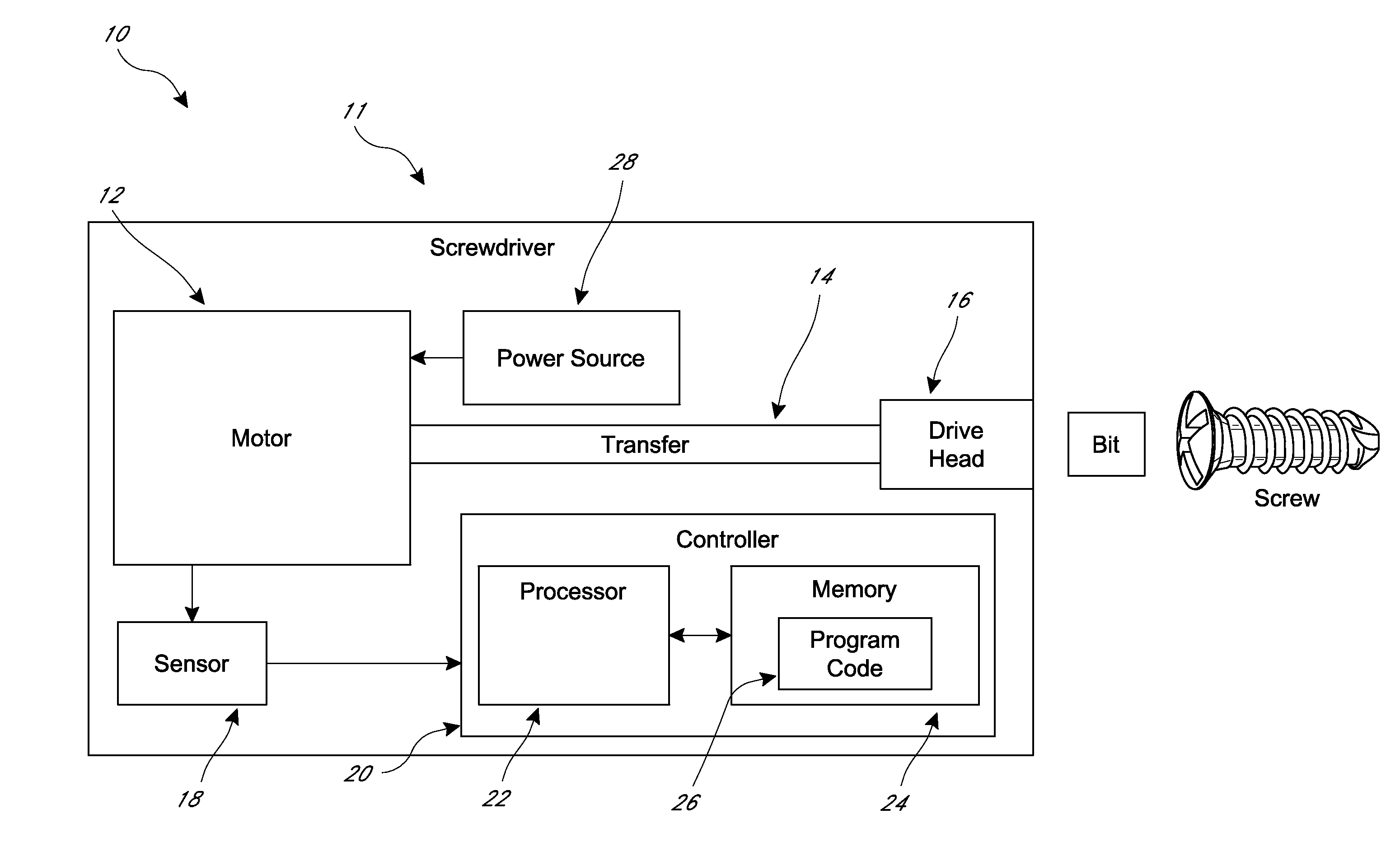
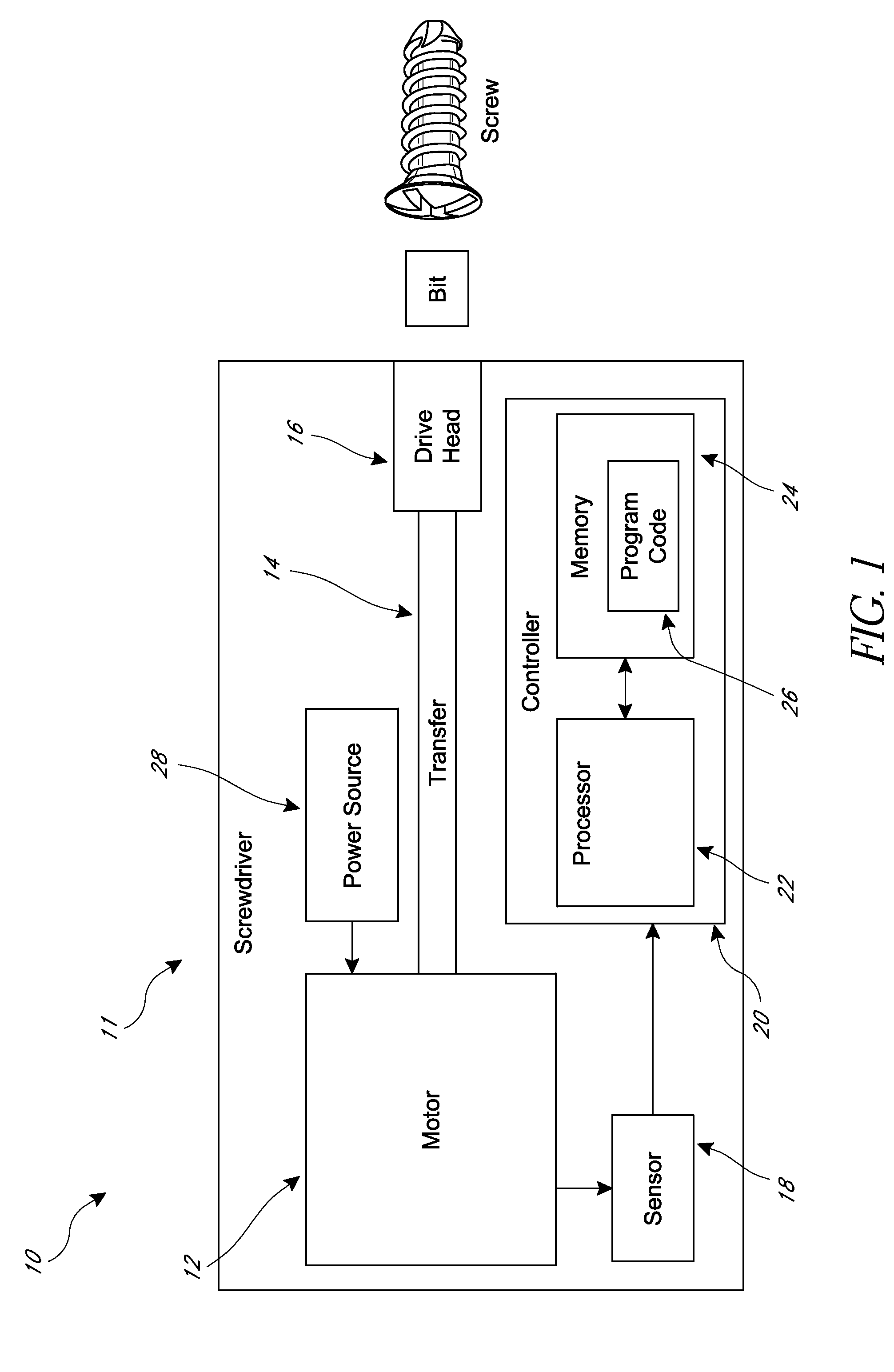
[0022]Various embodiments of a torque-limiting screwdriver 10 are disclosed. As more fully described below, the screwdriver 10 can determine when to stop a screw being driven into various types of bone so as to avoid stripping the screw in the bone. As shown in FIG. 1, the screwdriver includes a body 11 (also called a housing) that supports a motor 12. A transfer assembly 14 (e.g., one or more shafts, gears, etc.) operably connects the motor 12 to a drive head 16 at a distal end of the screwdriver 10 such that the motor 12 can turn the drive head 16. The drive head 16 can receive a bit, such as a crosshead bit, flathead bit, star bit (e.g., Torx), socket bit (e.g., hex), or otherwise. The bit in turn can be interfaced with a screw having a head with a corresponding shape. Thus, the screw can be positioned at a desired insertion location on a substrate (e.g., a bone) and the motor 12 can be operated to drive the screw into the substrate.

[0023]The screwdriver 10 can monitor and / or lim...


PUM


Abstract

Various torque-limiting screwdrivers, systems, and methods are disclosed. The screwdriver can include a body supporting a motor configured to rotate a screw engaged with the screwdriver. The screwdriver can include a controller configured to implement torque-limiting functionality, such as by monitoring the amount of torque applied to the screw and reducing or stopping rotation of the screw when certain torque-limiting criteria are met. Some embodiments include a threshold point, after which the torque-limiting functionality can be engaged. Some embodiments include a slowdown point, after which the rotational speed of the screw is reduced.

Description

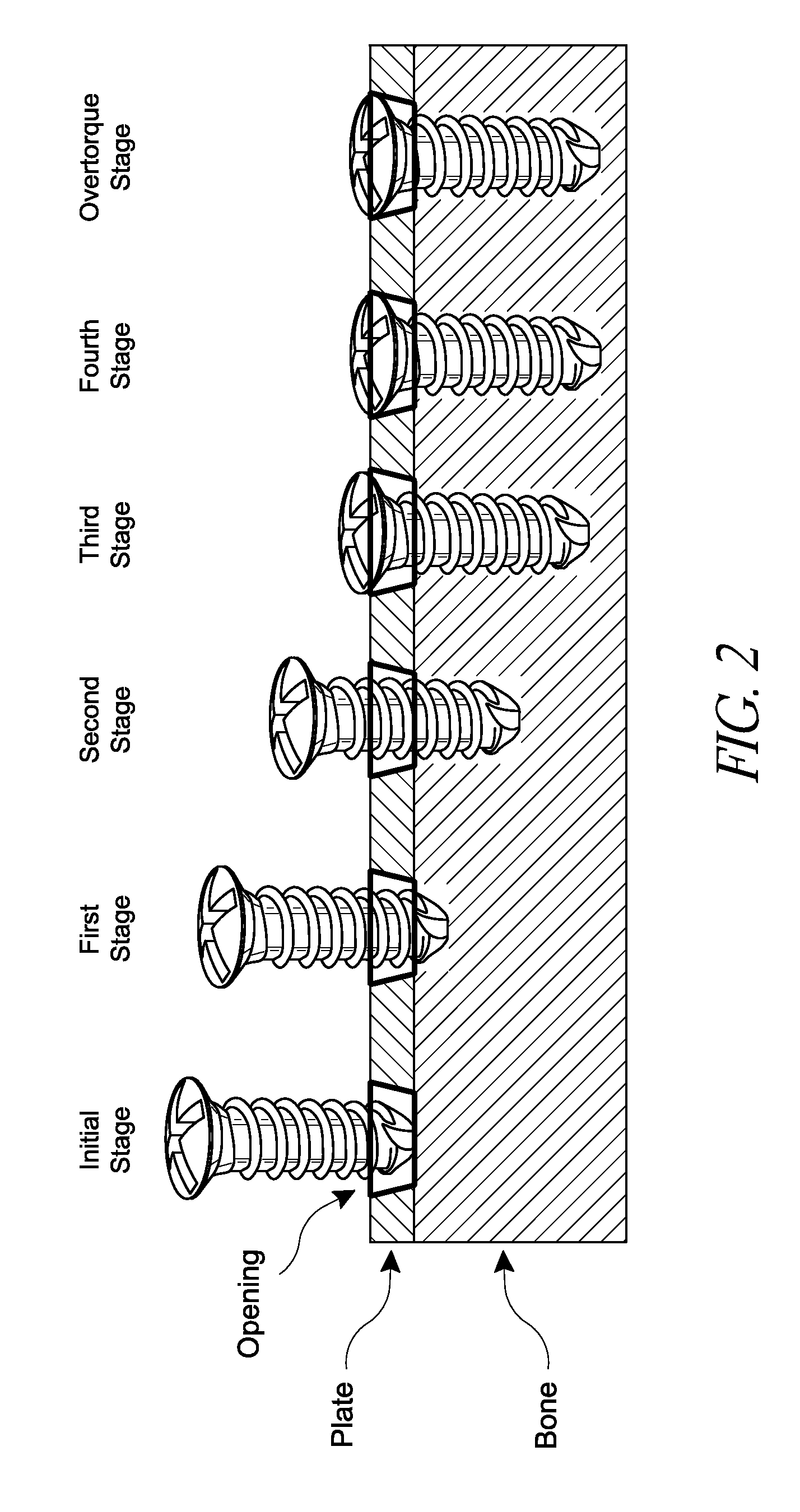
RELATED APPLICATIONS[0001]This application claims the benefit of U.S. Provisional Application No. 61 / 856,557, filed Jul. 19, 2013; U.S. Provisional Application No. 61 / 872,427, filed Aug. 30, 2013; U.S. Provisional Application No. 61 / 937,346, filed Feb. 7, 2014; and U.S. Provisional Application No. 61 / 940,197, filed Feb. 14, 2014. The entirety of each of the aforementioned applications is incorporated by reference herein.BACKGROUND[0002]1. Field[0003]This disclosure relates to torque-limiting devices, and in particular to embodiments of torque-limiting screwdrivers.[0004]2. Certain Related Art[0005]Various surgical procedures include inserting one or more screws into a bone to retain a structure, such as a plate, on the bone. During insertion, the screw is threaded into a bone and penetrates into the bone. With continued rotation, the screw seats on the plate, such as by a head of the screw contacting the plate. Still further rotation of the screw secures the screw against the plate ...

Claims


Application Information

Patent Timeline
Patent Type & Authority Patents(United States)
IPC IPC(8): A61B17/58B25B23/14B25B23/147B25B21/00A61B17/88A61F2/00A61B17/60
CPCA61B17/8875B25B21/002B25B23/14B25B23/147A61B2090/031A61B2017/00075
Inventor KUST, RICHARDDESROSIERS, JOHN JOSEPHSTEINMETZ, FRANCIS JAMESMA, DUNGDESAI, SIDDHARTH
Owner PRO DEX INC
Learn More