Pressure exchanger system

a technology of pressure exchanger and pressure exchanger, which is applied in the direction of reverse osmosis, multiple way valves, mechanical equipment, etc., can solve the problems of adverse effect on the efficiency of reverse osmosis systems, addition of losses, and substantial material stress on all components, and achieve reliable operation over a long period of time.

Inactive Publication Date: 2005-08-04
KSB AG
View PDF8 Cites 26 Cited by
  • Summary
  • Abstract
  • Description
  • Claims
  • Application Information

AI Technical Summary

Benefits of technology

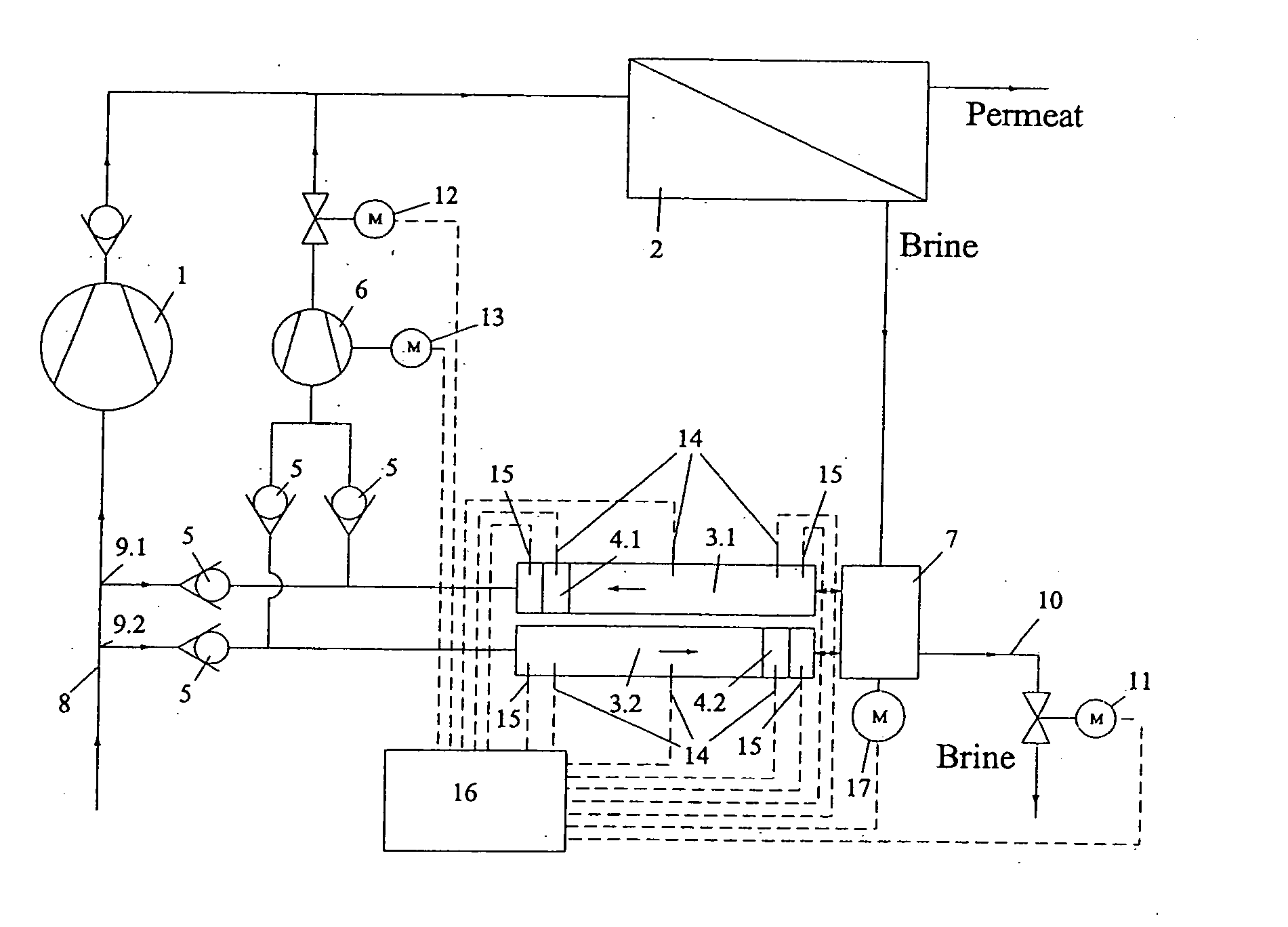
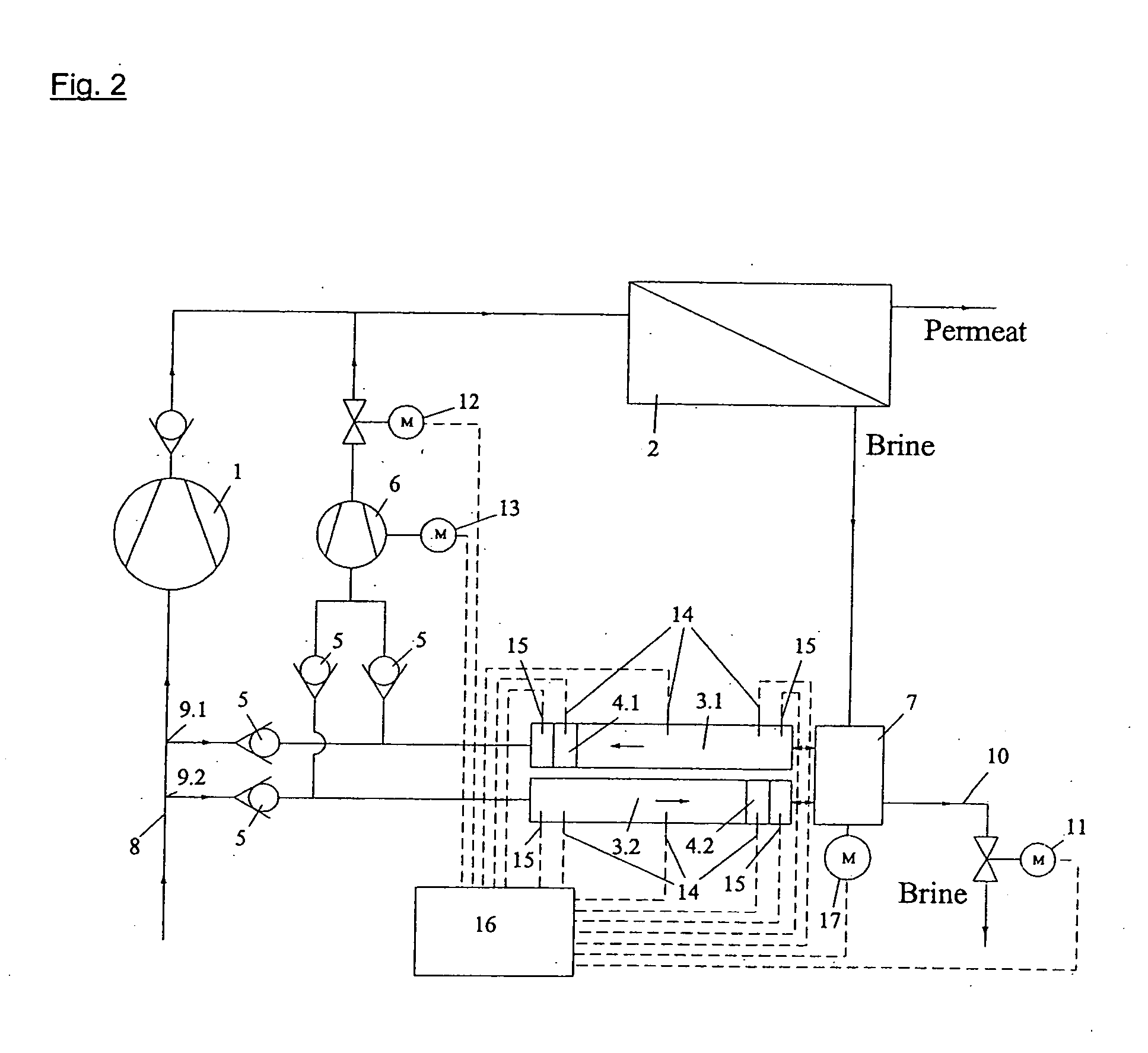
[0005] The present invention is directed toward providing a system that will be reliable in operation over a long period of time and will be capable of withstanding high loads for pressure exchanger systems having at least two tubular chambers and a driven reversing valve which is equipped with a rotating or linearly operable reversing element.

Problems solved by technology

However, this results in additional losses, which have an adverse effect on the efficiency of such a reverse osmosis system.
In the prior art devices, the alternating pressure loads and the resulting pressure surges produce a substantial material stress on all components.
This reduces the service life of the valves, the tubular chambers and any individual reversing valves and requires material-intensive construction, accordingly.
In addition, considerable annoying noises with negative consequences are produced during the reversing movements.
Such a high noise level requires additional complex noise suppression measures and safety measures.

Method used


Image

  • Pressure exchanger system
  • Pressure exchanger system
  • Pressure exchanger system

Examples


Embodiment Construction

[0021] For simplicity and illustrative purposes, the principles of the present invention are described hereinafter with reference to various illustrative embodiments thereof. Although the preferred embodiments of the invention are particularly disclosed herein, one of ordinary skill in the art will readily recognize that the same principles are equally applicable to, and can be implemented in other systems, and that any such variation would be within such modifications that do not depart from the true spirit and scope of the present invention. Before explaining the disclosed embodiments of the present invention in detail, it is to be understood that the invention is not limited in its application to the details of any particular arrangement shown, since the invention is capable of other embodiments. The terminology used herein is for the purpose of description and not of limitation.

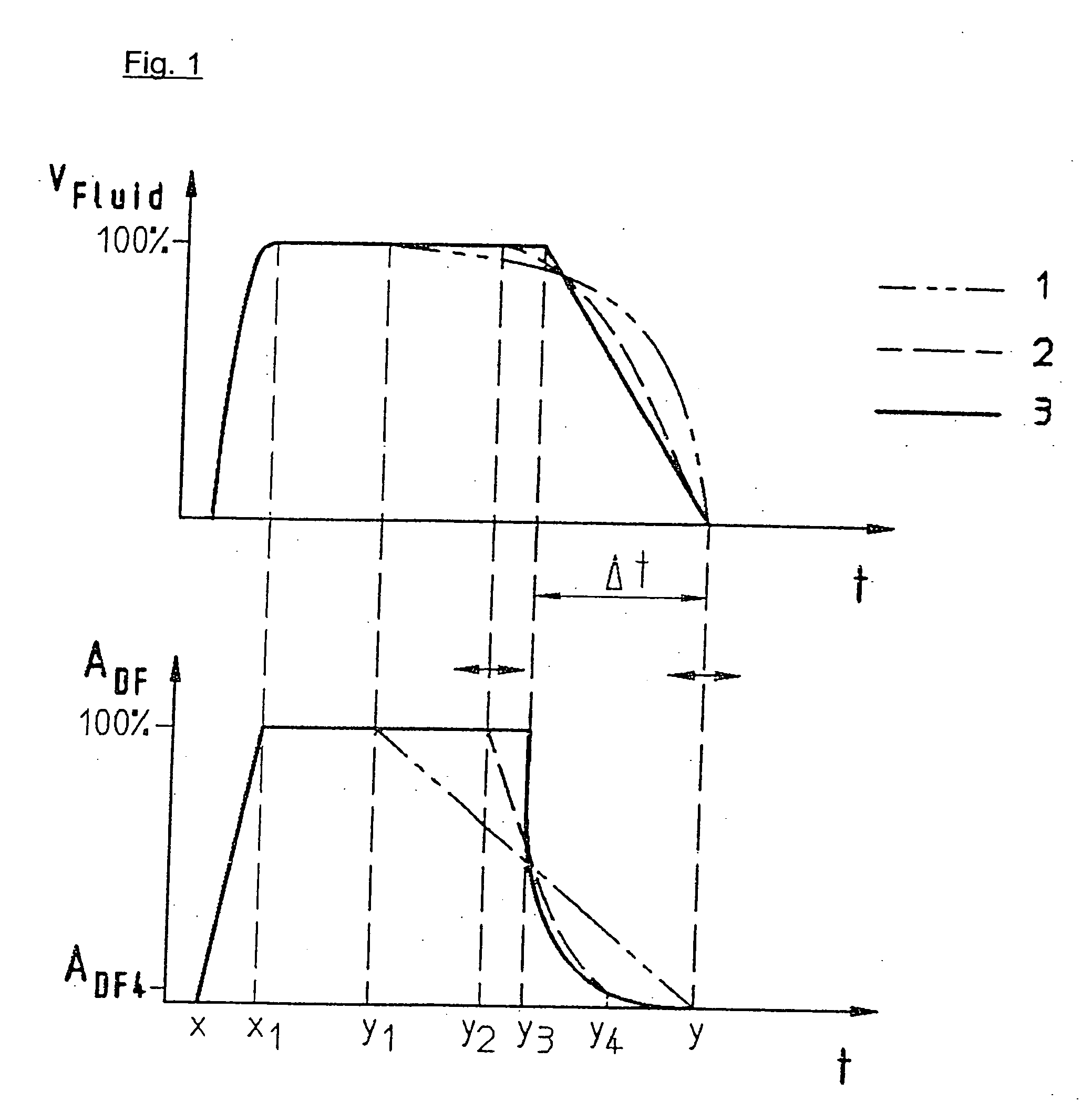
[0022] A variable and / or discontinuous movement sequence of a driven reversing element is illustrated...


PUM

PropertyMeasurementUnit
rate of movementaaaaaaaaaa
pressureaaaaaaaaaa
residence timeaaaaaaaaaa

Abstract

A pressure exchanger system having at least two tubular chambers, in which a plurality of reversing valves reverse the flow paths of fluid flows through the at least two tubular chambers. At least one driven reversing valve alternately reverses the flow paths between a supply source, which supplies a high-energy high-pressure fluid, and the tubular chambers. In reversing the liquid flows and shutting off previously open flow paths, the driven reversing element in the reversing valve executes a discontinuous or variable movement sequence.

Description

FIELD OF THE INVENTION [0001] The present invention relates generally to a pressure exchanger system and more particularly to a pressure exchanger system having at least two tubular chambers. Multiple reversing valves which reverse the flow paths of fluid flows through the at least two tubular chambers are provided. At least one driven reversing valve which alternately reverses the flow paths between the tubular chambers and a supply source which provides a high-energy high-pressure fluid are also provided. BACKGROUND OF THE INVENTION [0002] U.S. Pat. No. 5,306,428 describes a work exchanger system as part of a reverse osmosis system such that, with the help of this work exchanger system, energy is recovered from the fluid, called the brine, which leaves reverse osmosis modules but still has a high residual pressure. The work exchanger system has a reversing valve with a rotating reversing element with the help of which the tubular chambers to be filled or emptied are switched. The ...

Claims


Application Information

Patent Timeline
Patent Type & Authority Applications(United States)
IPC IPC(8): B01D61/06B01D61/10C02F1/44F04B9/117F04F99/00F15B3/00F16K11/00
CPCB01D61/06F04B2201/0201F04B9/1176Y10T137/86839
Inventor BRUECKMANN, FREDKNOEBL, WILTRUDBRUHNS, UWEKOCHANOWSKI, WOLFGANG
Owner KSB AG
Why Eureka
Try Eureka