Inlet port mechanism for introducing object and treatment system

a technology of inlet port and treatment system, which is applied in the direction of thin material processing, loading/unloading, and article separation, etc., can solve the problems of reducing throughput, affecting the flow rate of injected inert gas, and affecting the insertion of object, so as to achieve rapid and smooth operation, reduce the momentum or the flow rate of injected inert gas, and improve the effect of throughpu

Inactive Publication Date: 2009-04-09
TOKYO ELECTRON LTD
View PDF17 Cites 24 Cited by
  • Summary
  • Abstract
  • Description
  • Claims
  • Application Information

AI Technical Summary

Benefits of technology

[0018]The inlet port mechanism and the treatment system according to the present invention provide the following excellent effects. That is, the inert gas is injected from the gas injection means having the cylindrical porous gas injection tube that extends along the inner periphery of the opening gate and is made of the porous material. In this configuration, the inert gas is injected from the entire surface of the porous gas injection tube. Therefore, the momentum or the flow rate of the injected inert gas can be sufficiently reduced. The replacement of the atmosphere present in the storage container body with the inert gas can be quickly and smoothly performed to improve the throughput without shifting of the position of the object.

Problems solved by technology

The momentum of the injected gas may cause the wafer to be blown or cause the position of the wafer to be shifted.
Due to the suppression, it takes much time to replace the inert gas with the atmosphere present in the storage container body.
This results in a reduction in throughput.
In addition, the introduced inert gas may leak to an area where an operator works.
Thus, the momentum of the N2 gas prevails still, and the position of the wafer may be shifted due to undesirable motion of the wafer.

Method used


Image

  • Inlet port mechanism for introducing object and treatment system
  • Inlet port mechanism for introducing object and treatment system
  • Inlet port mechanism for introducing object and treatment system

Examples


experimental example

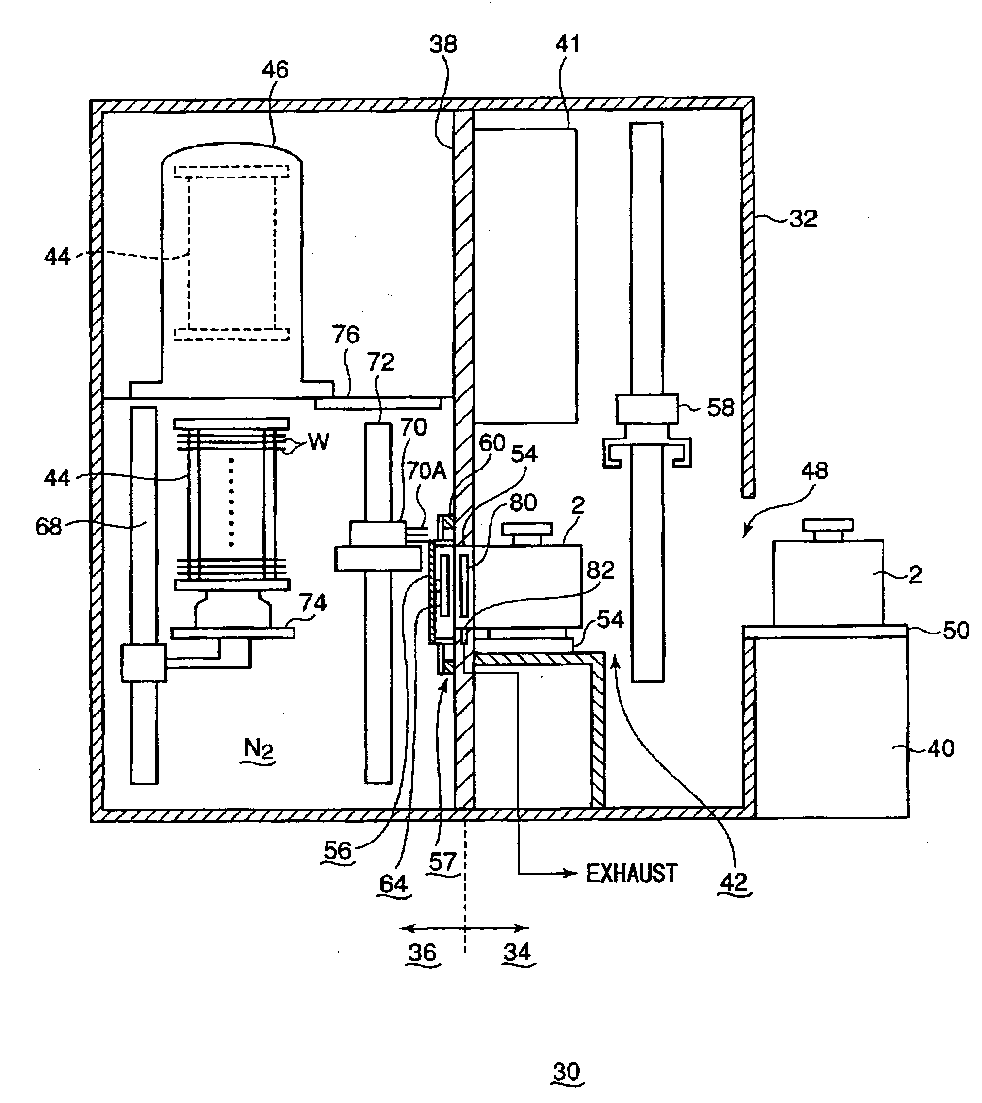
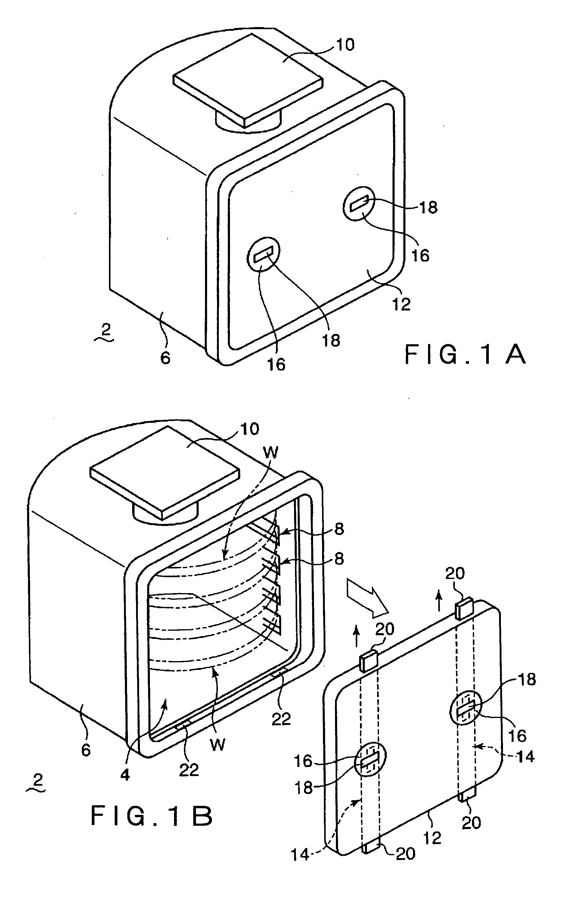
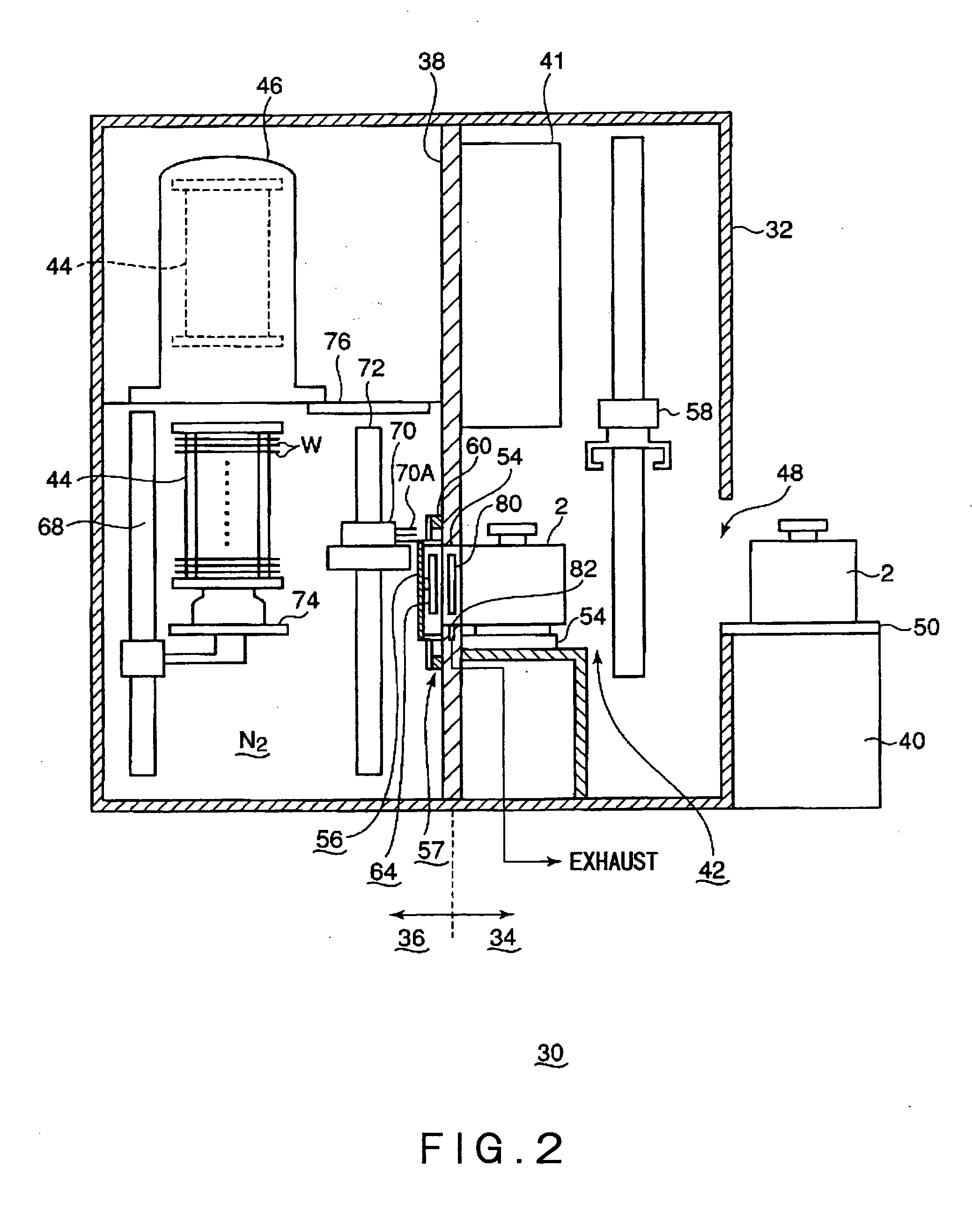
[0080]A comparative experiment was performed using the inlet port mechanism for introducing an object to be treated according to the embodiment of the present invention and a conventional inlet port mechanism for introducing an object to be treated. The evaluation results of the comparative experiment will be described. A storage container body 2 used in the comparative experiment is capable of storing 25 wafers each having a diameter of 300 mm. The flow amount of an N2 gas was set to be greatest within such an extent that the wafers W did not shake due to the flow rate of the N2 gas.

[0081]In the case where the conventional inlet port mechanism was used, the flow amount of the N2 gas was approximately 60 L / min. to 90 L / min, and it took 145 seconds to 170 seconds to reduce the concentration of oxygen present in the storage container body 2 to a standard value. In the case where the inlet port mechanism according to the present invention was used, it was possible to feed the N2 gas wi...


PUM


Abstract

An inlet port mechanism for an object to be treated is provided to quickly and smoothly replace an atmosphere in a storage container body with an inert gas without shifting of the position of the object to be treated. The inlet port mechanism has a partition wall, a stage, an opening/closing door mechanism, a lid opening/closing mechanism, a gas injection unit, and an exhaust unit. The partition wall partitions a space into a container transfer area and an object transfer area and has an opening gate. The storage container body storing the object is placed on the stage. The opening/closing door mechanism has an opening/closing door that serves to open and close the opening gate. The lid opening/closing mechanism is provided with the opening gate and serves to open and close an opening/closing lid of the storage container body. The gas injection unit extends along an inner periphery of the opening gate to inject an inert gas into the storage container body and has a porous gas injection tube made of a porous material and having a cylindrical shape. The exhaust unit has an exhaust port for exhausting an atmosphere that is present in the storage container body and purged by the inert gas.

Description

CROSS-REFERENCE TO RELATED APPLICATION[0001]The present application benefits from Japanese application JP2007-259689, filed on Oct. 3, 2007, the disclosure of which is hereby incorporated by reference in its entirety.BACKGROUND OF THE INVENTION[0002]1. Field of the Invention[0003]The present invention relates to an inlet port mechanism for introducing an object to be treated, such as a semiconductor wafer, from a storage container body for storing the object in an airtight manner into an object transfer area, and to a treatment system using the mechanism.[0004]2. Background Art[0005]In general, a film formation process, an oxidation treatment, a diffusion treatment, an etching treatment, and the like are repeatedly performed on a semiconductor wafer for manufacture of semiconductor integrated circuits such as an IC and LSI. In order to perform such a treatment, it is necessary that the semiconductor wafer be transferred from one apparatus to another apparatus.[0006]In this case, in ...

Claims


Application Information

Patent Timeline
Patent Type & Authority Applications(United States)
IPC IPC(8): H01L21/02B65G65/00
CPCH01L21/67017H01L21/67775H01L21/67772H01L21/67389H01L21/02
Inventor OYAMA, KATSUHITONITADORI, HIROMITAKEUCHI, YASUSHI
Owner TOKYO ELECTRON LTD
Why Eureka
Try Eureka