

Multifunctional cardiovascular nursing bed
A cardiovascular and nursing bed technology, which is applied in the field of medical equipment, can solve the problems of manual lifting and lowering of nursing beds, and achieve the effects of convenient infusion treatment, saving time and labor, and improving efficiency
- Summary
- Abstract
- Description
- Claims
- Application Information
AI Technical Summary
Problems solved by technology
Method used
Image

Examples
Embodiment 1
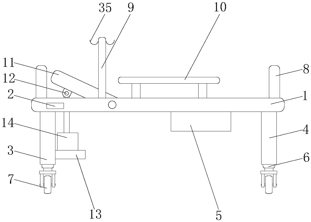
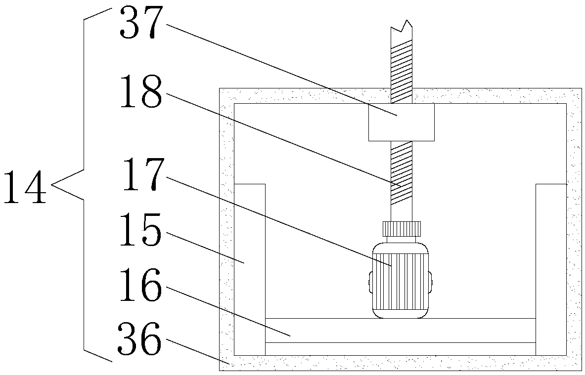
[0025] Example 1 please refer to figure 2 , the lifting device 14 comprises a lifting box 36, the inner wall of the lifting box 36 is symmetrically provided with chute 15, between the chute 15 is provided with a slide plate 16 used in conjunction with the chute 15, and the top of the slide plate 16 is fixedly equipped with a first motor 17. The output shaft of the first motor 17 is fixedly connected with a screw rod 18, and the end of the screw rod 18 away from the output shaft of the first motor 17 runs through the lifting box 36 and the bed board 1 in sequence and is movably connected with the first connecting block 12. The lifting box 36 The top of the inner wall is fixedly provided with a threaded block 37 used in conjunction with the screw mandrel 18, and the controller 2 is electrically connected with the first motor 17. When in use, the controller 2 is used to control the operation of the first motor 17, and the first motor 17 drives the wire Rod 18 rotates, and screw ...
Embodiment 2
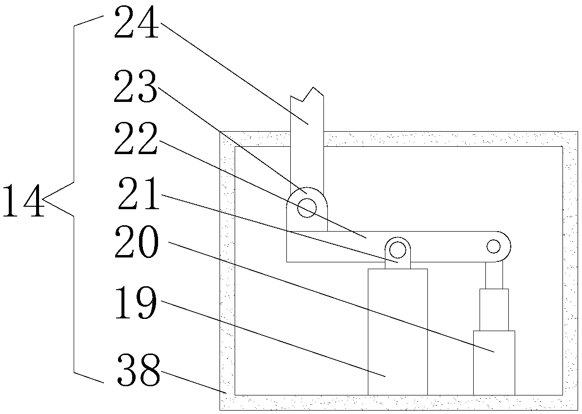
[0026] Example 2 please refer to image 3 , the lifting device 14 includes a housing 38, the bottom of the inner wall of the housing 38 is sequentially installed with a support column 19 and an automatic telescopic rod 20 from left to right, the top of the support column 19 is fixedly connected with a second connecting block 21, and the second connecting block 21 The upper movable plate 22 is movably connected, and the top of the automatic telescopic rod 20 is movably connected with the right side of the movable plate 22, and the left side of the top of the movable plate 22 is fixedly connected with a third connecting block 23, and the third connecting block 23 is movably connected with a connecting block 23. rod 24, and the end of the connecting rod 24 away from the third connecting block 23 runs through the housing 38 and the bed board 1 in sequence and is movably connected with the first connecting block 12. The controller 2 is electrically connected with the automatic teles...
Embodiment 3
[0027] Example three please refer to Figure 4 , the lifting device 14 includes a box body 39, the inside of the box body 39 is provided with a support plate 25, and both sides of the support plate 25 are fixedly connected with both sides of the inner wall of the box body 39, and the top of the inner wall of the box body 39 is fixedly connected with a fixed column 26, and the top of the fixed column 26 is fixedly connected to the top of the inner wall of the box body 39, the fixed column 26 is located in front of the support plate 25, and the inside of the fixed column 26 is provided with a lifting rod 27, and one side of the lifting rod 27 is fixedly connected with a rack 28, both sides of the rack 28 are connected with the limit block 29, the top of the elevating rod 27 passes through the box body 39 and the bed board 1 in turn and is movably connected with the first connecting block 12, the top of the support plate 25 is equipped with a second motor 30, The output shaft of ...
PUM
 Abstract
Description
Claims
Application Information