A method for controlling rough rolling width of slab
What is AI technical title?
AI technical title is built by PatSnap AI team. It summarizes the technical point description of the patent document.
A technology of width control and rough rolling, applied in rolling mill control devices, metal rolling, metal rolling, etc., can solve the problem of low control precision of slab width, reduce manual intervention, improve width control precision, and improve control ability Effect
Active Publication Date: 2020-01-31
BAOSHAN IRON & STEEL CO LTD
View PDF5 Cites 0 Cited by
Summary
Abstract
Description
Claims
Application Information
AI Technical Summary
This helps you quickly interpret patents by identifying the three key elements:
Problems solved by technology
Method used
Benefits of technology
Problems solved by technology
It is used to solve the problem of low accuracy of slab width control due to manual intervention in the existing rough rolling width control method
Method used
Image
Click on the blue label to locate the original text in one second.
Reading with bidirectional positioning of images and text.
PUM
Abstract
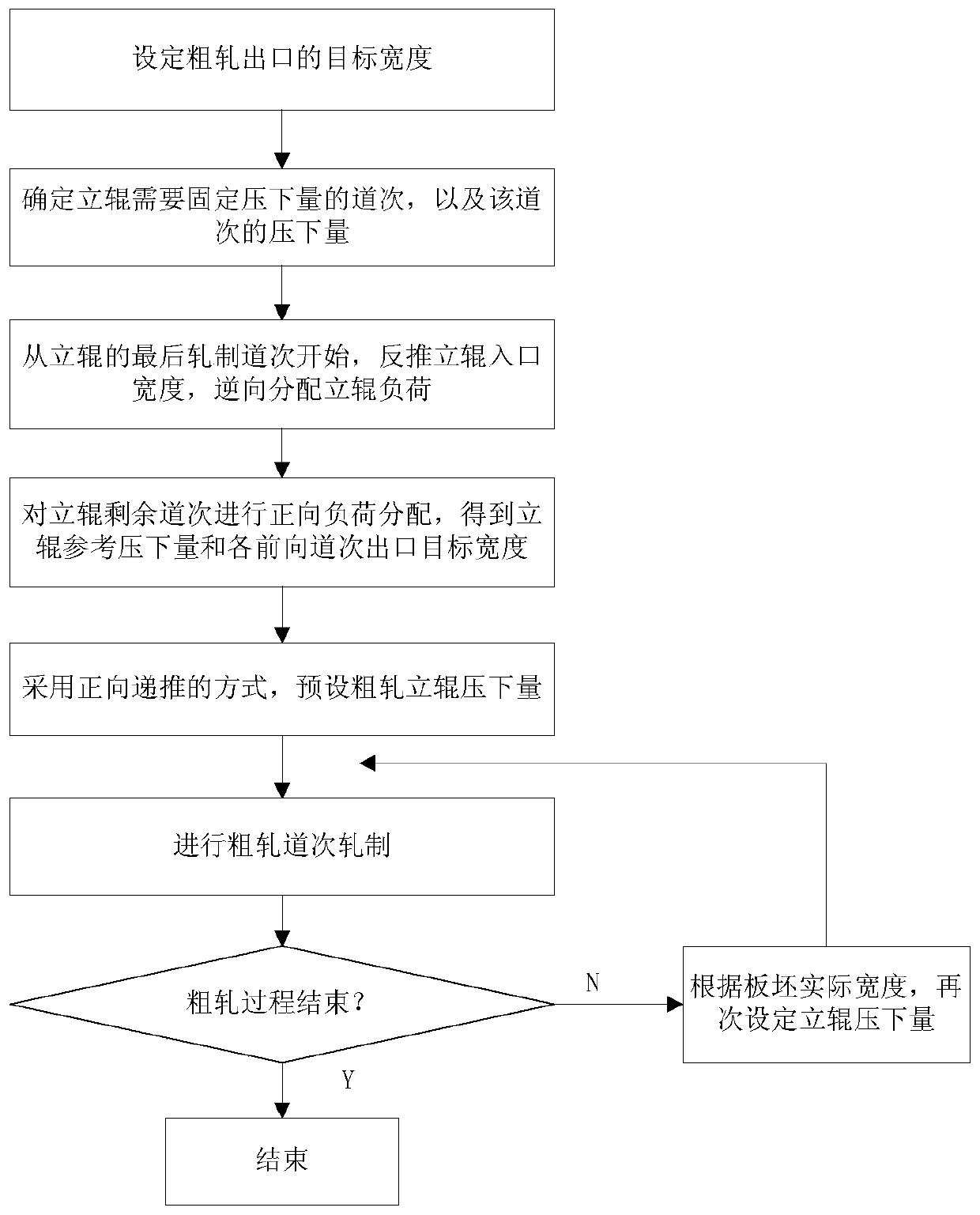
The invention relates to a rough rolling width control method of a plate blank. According to the rough rolling width control target, firstly, the pass of rolling reduction needing to be fixed by a vertical roll and the rolling reduction of the pass are determined according to needs; then, starting from the last rolling pass of the vertical roll, the inlet width of the vertical roll is reversely pulled to be used as the target width of the previous pass or several passes according to the rolling reduction, and vertical roll loads of one or more passes is distributed reversely; finally, the restof passes of the vertical roll is subjected to forward load distribution; and after the plate blank completes rolling of every pass, rolling recalculation is started, and the rolling reduction of thevertical roll is re-set according to newest production information. According to the method, the measured value generated after rolling of the plate blank can be utilized more effectively, manual intervention of operation workers can be greatly reduced, the width control precision can be obviously improved, and the problem that the width control precision of a plate blank is low due to manual intervention in an existing rough rolling width control method is solved.
Description
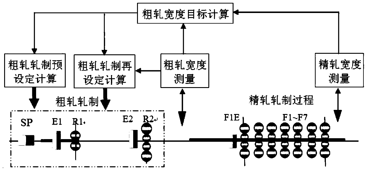
technical field [0001] The invention relates to the technical field of hot rolling, in particular to a rough rolling width control method of a slab. Background technique [0002] At present, hot rolling and rough rolling generally use two rolling mills, such as figure 1 , The two rolling mills include two vertical rolling mills E1 and E2. The general principle of rough rolling vertical roll load distribution is that the rough rolling rolls the slab to the target width in the first pass of the E1 large vertical roll, and the rolling target of each forward pass of the subsequent vertical roll maintains the R2 exit width, That is to say, each forward pass of rough rolling is based on the target width of R2 exit, and the entry width of each pass is side-pressed by E1 and E2 vertical rolls, and the target width of R2 exit is reached after horizontal rolling by R1 or R2. . Another method using equal proportion weighting of roughing load, such as patent No. 201310005629, the met...
Claims
Application Information
Patent Timeline
Application Date:The date an application was filed.
Publication Date:The date a patent or application was officially published.
First Publication Date:The earliest publication date of a patent with the same application number.
Issue Date:Publication date of the patent grant document.
PCT Entry Date:The Entry date of PCT National Phase.
Estimated Expiry Date:The statutory expiry date of a patent right according to the Patent Law, and it is the longest term of protection that the patent right can achieve without the termination of the patent right due to other reasons(Term extension factor has been taken into account ).
Invalid Date:Actual expiry date is based on effective date or publication date of legal transaction data of invalid patent.

