Welding device for welding steel trusses

A technology of welding device and steel truss, which is applied in the direction of welding equipment, auxiliary equipment, auxiliary welding equipment, etc., can solve the problems of poor welding angle, low efficiency, and affecting the quality of use, so as to facilitate operation, improve quality, and improve welding efficiency Effect

Active Publication Date: 2019-07-19
北京城建精工钢结构工程有限公司
View PDF5 Cites 0 Cited by
  • Summary
  • Abstract
  • Description
  • Claims
  • Application Information

AI Technical Summary

Problems solved by technology

[0004] The technical problem to be solved by the present invention is that the existing truss needs to be welded with multiple steel frames with different angles, and many people are needed to support the welding, and the welding angle is poor, so it is not only inefficient, but also affects the quality of later use , the purpose is to provide a welding device for welding steel trusses, to solve the problem of welding steel pipes for trusses

Method used


Image

  • Welding device for welding steel trusses
  • Welding device for welding steel trusses
  • Welding device for welding steel trusses

Examples


Embodiment 1

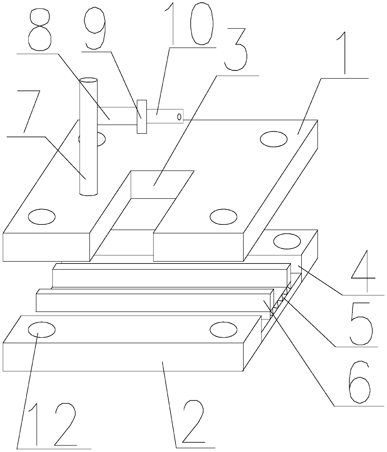
[0030] Such as figure 1 and figure 2As shown, the welding device for welding steel trusses of the present invention includes steel pipes for welding trusses and fixing devices for fixing steel pipes. The fixing devices include a first fixing plate 1 and a second fixing plate 2, and the first fixing plate 1 is located directly above the second fixed plate 2, and the first fixed plate 1 is provided with a first groove 3 on a horizontal plane with one end penetrating through the side of the first fixed plate 1 and the other end inside the first fixed plate 1. The two fixed plates 2 are provided with second grooves 4 on the horizontal plane with two ends penetrating through the opposite two sides of the second fixed plate 2, and the inner bottom surface of the second grooves 4 can be arranged along the width of the second grooves 4. direction telescopic spring plate 5, the two ends of spring plate 5 telescopic ends are all vertically connected with fixed plate 6, the distance be...

Embodiment 2

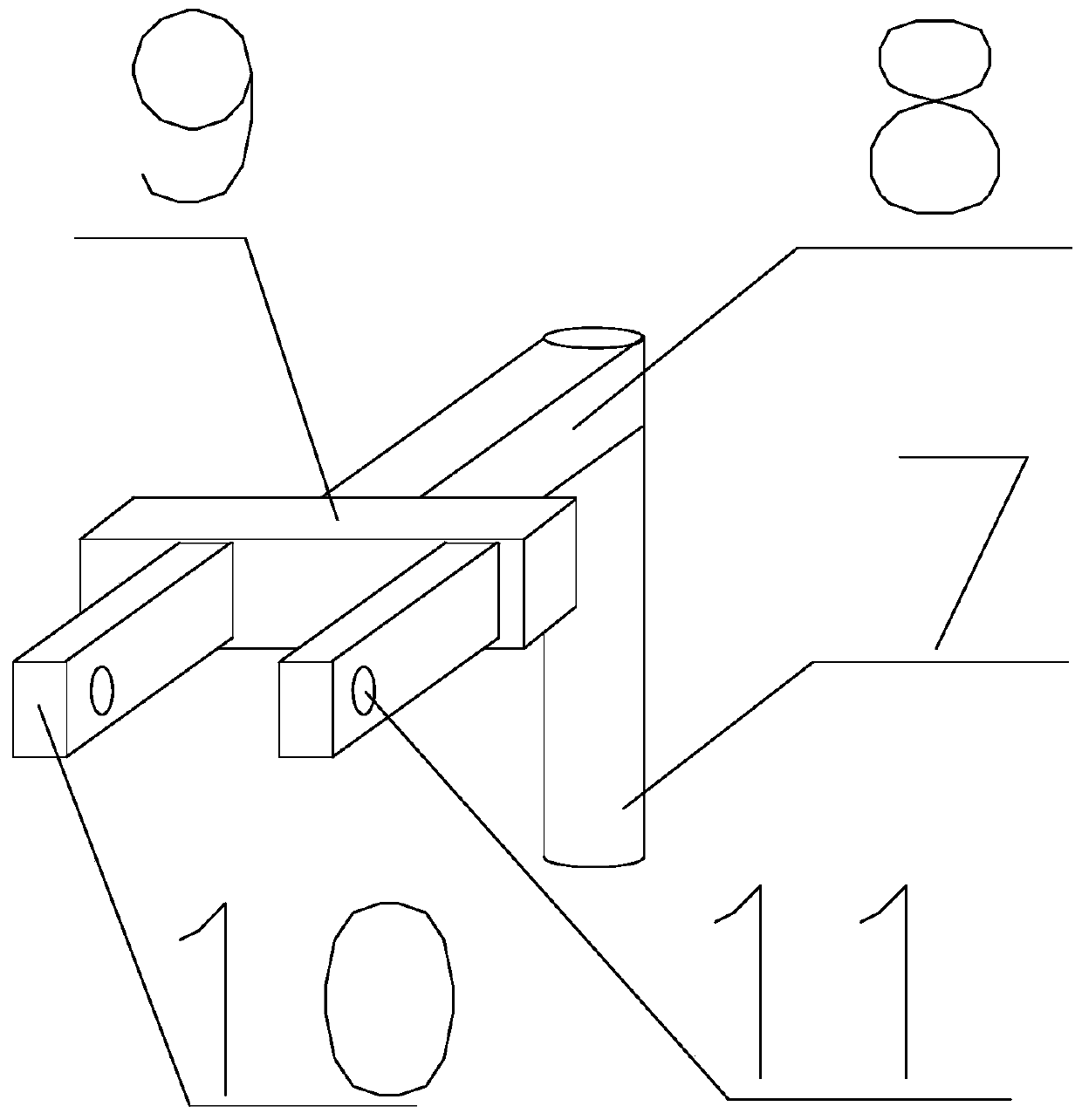
[0032] The welding device for welding steel trusses, on the basis of Embodiment 1, the clamping device includes two connecting plates 10 vertically arranged on the first support rod 9 at one end, the connecting plates 10 are located on the horizontal plane, and are located in the first concave Above the groove 3, a chute on the horizontal plane is provided on the surface connecting the first support rod 9 and the connecting plate 10, one end of the connecting plate 10 slides along the direction of the chute, and the other end of the connecting plate 10 is provided with a fixed Groove 11, fixing groove 11 is fixedly connected through bolt penetration, steel pipe is fixed between two connecting plates 10, connecting plate 10 slides along the chute, and is fixedly connected to the steel pipe that is located in between through fixing groove 11 by bolt. Several convex lines are arranged on two opposite surfaces of the connecting plate 10, and the convex lines are made of rubber mate...

Embodiment 3

[0034] A welding device for welding steel trusses, the horizontal sections of the first fixed plate 1 and the second fixed plate 2 are squares of the same size, and the four through grooves 12 on the first fixed plate 1 and the second fixed plate 2 are surrounded by into squares of equal size. When welding three steel pipes on the same plane, one end of steel pipe A and steel pipe B are in contact with each other and connected with the side of steel pipe C, and the angles between steel pipe A, steel pipe B and steel pipe C are all 45 degrees. The steel pipe C is placed between two fixed plates 6, fixedly connected by the spring plate 5, then the steel pipe A is clamped on the clamping device, and the lengths of the first telescopic rod 7 and the second telescopic rod 8 are adjusted to make the steel pipe The lower end of A is in contact with the side of steel pipe C, and the angle between steel pipe A and steel pipe C is 45 degrees. Rotate the connecting rod as needed so that ...


PUM


Abstract

The invention discloses a novel welding device for welding a steel truss. One of the two steel pipes for welding is horizontally and fixedly placed between two fixing plates, and the other one is placed into a first groove in an inclined manner, and is fixed by a clamping device, wherein the inclination angle of the second steel pipe is adjusted by adjusting the length of a first telescopic pipe and the length of a second telescopic pipe; identical through grooves are formed in the four corners of the first fixing plate and the four corners of the second fixing plate respectively, a connectingrod is arranged between two through grooves on the same vertical straight line in the first fixing plate in a connected manner as the same in the second fixing plate, and the distance between the first fixing plate and the second fixing plate is adjusted through the connecting rods so as to enable welding points of two steel pipes make contact with each other and located in an interval between the first fixing plate and the second fixing plate. The novel welding device for welding the steel truss is simple in structure, and convenient to operate and use.

Description

technical field [0001] The invention relates to the field of construction, in particular to a welding device for welding steel trusses. Background technique [0002] Steel trusses refer to trusses made of steel, roof structures such as crane girders, bridges, and hydraulic gates for industrial and civil buildings. Steel trusses are commonly used as the main load-bearing components. Various towers, such as mast towers, TV towers and transmission line towers, are commonly used as space steel trusses composed of three-sided, four-sided or multi-sided planar trusses. The most commonly used is the plane truss, and its stress is essentially a lattice beam under the action of lateral load. Compared with the steel beam of the solid web type, the steel truss is characterized by replacing the flange with the chord and the web with the web, and connecting the web at each node through the gusset plate (or other parts) with welds or other connections. The rods and chords are connected ...

Claims


Application Information

Patent Timeline
Patent Type & Authority Patents(China)
IPC IPC(8): B23K37/04
CPCB23K37/0435
Inventor 黄欢
Owner 北京城建精工钢结构工程有限公司
Why Eureka
Try Eureka