Reinforcing steel bar welding equipment

A technology for welding equipment and steel bars, applied in welding equipment, auxiliary welding equipment, welding/cutting auxiliary equipment, etc., can solve the problems of reduced work efficiency, poor welding effect, and laborious transmission, so as to improve work efficiency and weld good effect, good effect

Active Publication Date: 2018-12-07
GUANGDONG BOZHILIN ROBOT CO LTD
View PDF11 Cites 4 Cited by
  • Summary
  • Abstract
  • Description
  • Claims
  • Application Information

AI Technical Summary

Problems solved by technology

[0003] However, when the existing steel bar welding equipment transmits the steel bar, it can only rely on manpower to transmit the steel bar. After the steel bar is welded, the welding point of the steel bar cannot be squeezed, so that the welding point of the steel bar is not firmly welded, and the welding effect is not good, and when the existing steel bar welding equipment welds the steel bar, the angle of the welding head cannot be adjusted. Make the use of steel bar welding equipment not effective

Method used


Image

  • Reinforcing steel bar welding equipment
  • Reinforcing steel bar welding equipment
  • Reinforcing steel bar welding equipment

Examples


Embodiment Construction

[0022] The following will clearly and completely describe the technical solutions in the embodiments of the present invention with reference to the accompanying drawings in the embodiments of the present invention. Obviously, the described embodiments are only some of the embodiments of the present invention, not all of them. Based on the embodiments of the present invention, all other embodiments obtained by persons of ordinary skill in the art without making creative efforts belong to the protection scope of the present invention.

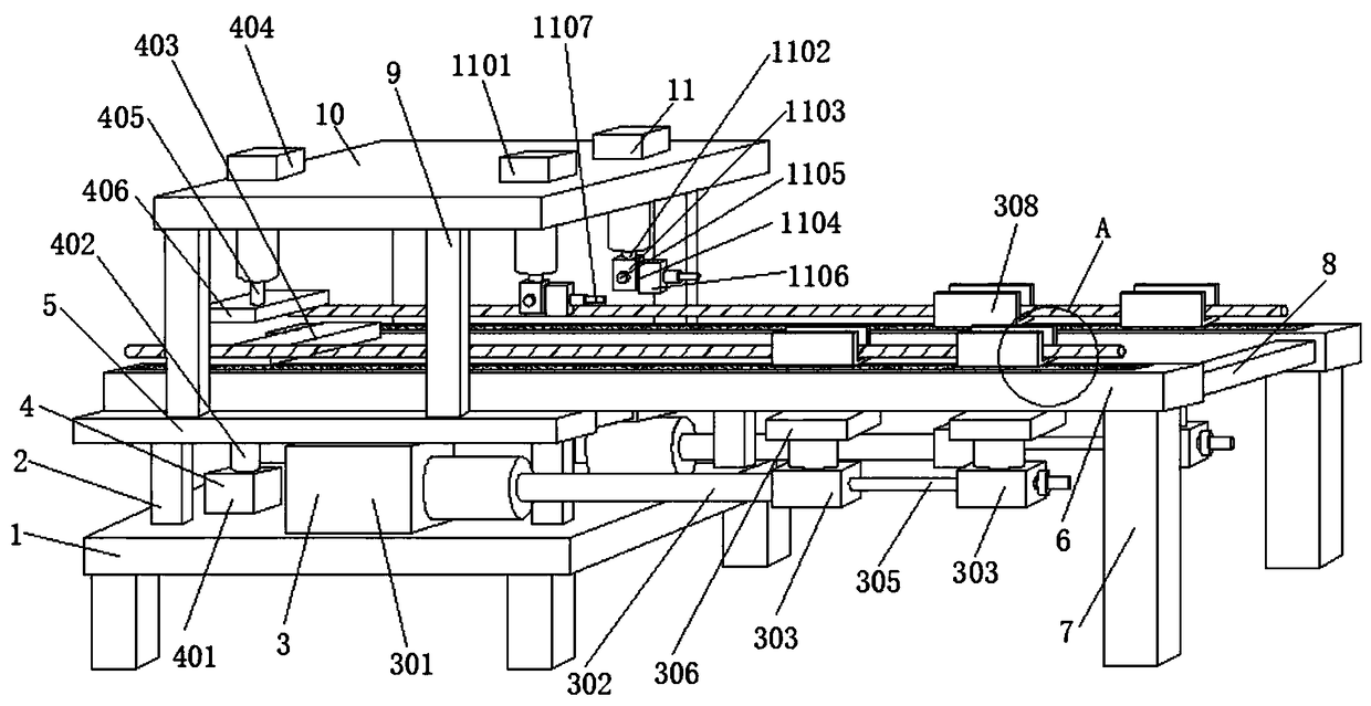
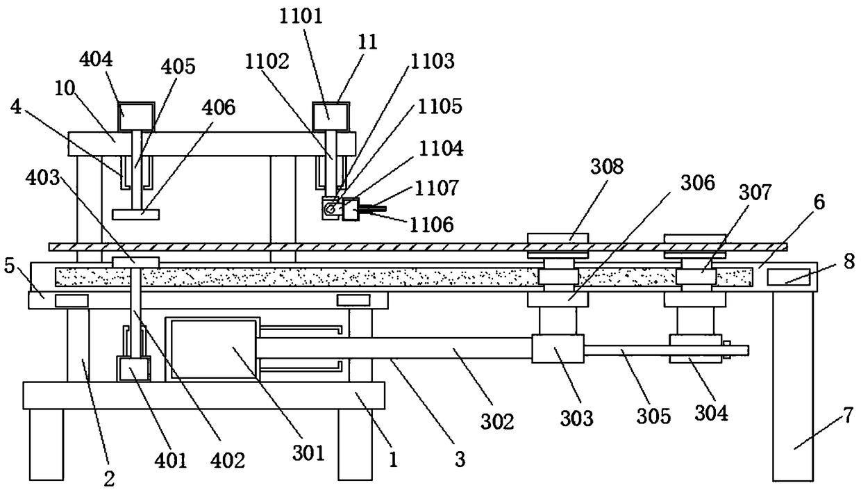
[0023] see Figure 1-6 , an embodiment provided by the present invention: a steel bar welding equipment, including a base plate 1, the four corners of the top of the base plate 1 are provided with support legs 2, the top of the support legs 2 is provided with a first support plate 5, the top of the base plate 1 One end is provided with a transmission mechanism 3, and the number of transmission mechanisms 3 is two groups. The side of the bottom pl...


PUM


Abstract

The invention discloses reinforcing steel bar welding equipment which comprises a base plate. Supporting legs are arranged at the four corners of the top of the base plate, a first supporting plate isarranged on the tops of the supporting legs, two sets of conveying mechanisms are arranged at one end of the top of the base plate, an extruding mechanism is arranged on the side, far away from the conveying mechanisms, of the base plate, fourth supporting rods are arranged at the four corners of the top of the first supporting plate, and second supporting plates are arranged on the tops of the fourth supporting rods. According to the reinforcing steel bar welding equipment, a second air cylinder pushes a second push rod to drive a first pressing plate to move upwards, meanwhile, a third aircylinder pushes a third push rod to enable a second pressing plate on the third push rod to move downwards, the tops and bottoms of welded reinforcing steel bars are extruded, the welding points of the reinforcing steel bars are welded more firmly, and the welding effect is better; and a pin shaft is arranged, so that a welding head rotates with the pin shaft as a base point, the angle of the welding head is adjusted accordingly, and the using effect of the reinforcing steel bar welding equipment is better.

Description

technical field [0001] The invention relates to the technical field of steel bar welding machinery, in particular to a steel bar welding equipment. Background technique [0002] Steel bar connection refers to the connection method of steel bars. There are four main connection methods of steel bars: lap joint, mechanical connection, casing grouting connection and welding. The most commonly used method is steel bar connection. [0003] However, when the existing steel bar welding equipment transmits the steel bar, it can only rely on manpower to transmit the steel bar. After the steel bar is welded, the welding point of the steel bar cannot be squeezed, so that the welding point of the steel bar is not firmly welded, and the welding effect is not good, and when the existing steel bar welding equipment welds the steel bar, the angle of the welding head cannot be adjusted. Make the use effect of steel bar welding equipment bad. Contents of the invention [0004] The object o...

Claims


Application Information

Patent Timeline
Patent Type & Authority Applications(China)
IPC IPC(8): B23K37/047B23K37/02
CPCB23K37/02B23K37/047
Inventor 杨泓斌张亮亮王云燕黄万禧刘博
Owner GUANGDONG BOZHILIN ROBOT CO LTD
Why Eureka
Try Eureka