Drilling device for workpieces with special-shaped structures

A technology of drilling device and workpiece, which is applied to drilling dies, positioning devices, metal processing machine parts and other directions for workpieces, can solve the problems of difficulty in guaranteeing the size of direct drilling, difficulty in guaranteeing the position, and poor interchangeability, etc. Achieve the effect of simple and novel structure, simple and compact structure, and ensure dimensional accuracy

Pending Publication Date: 2018-12-07
TIANJIN RAILWAY SIGNAL
View PDF12 Cites 2 Cited by
  • Summary
  • Abstract
  • Description
  • Claims
  • Application Information

AI Technical Summary

Problems solved by technology

Due to its special-shaped structure, it is difficult to guarantee the position of the drilling positioning fixture on the market, and it is not eas...

Method used


Image

  • Drilling device for workpieces with special-shaped structures
  • Drilling device for workpieces with special-shaped structures
  • Drilling device for workpieces with special-shaped structures

Examples


Embodiment Construction

[0035] It should be noted that, in the case of no conflict, the embodiments of the present invention and the features in the embodiments can be combined with each other.

[0036] In describing the present invention, it should be understood that the terms "center", "longitudinal", "transverse", "upper", "lower", "front", "rear", "left", "right", " The orientations or positional relationships indicated by "vertical", "horizontal", "top", "bottom", "inner" and "outer" are based on the orientations or positional relationships shown in the drawings, and are only for the convenience of describing the present invention and Simplified descriptions, rather than indicating or implying that the referred device or element must have a particular orientation, be constructed, and operate in a particular orientation, are therefore not to be construed as restrictive to the invention. In addition, the terms "first", "second", etc. are used for descriptive purposes only, and should not be unders...


PUM


Abstract

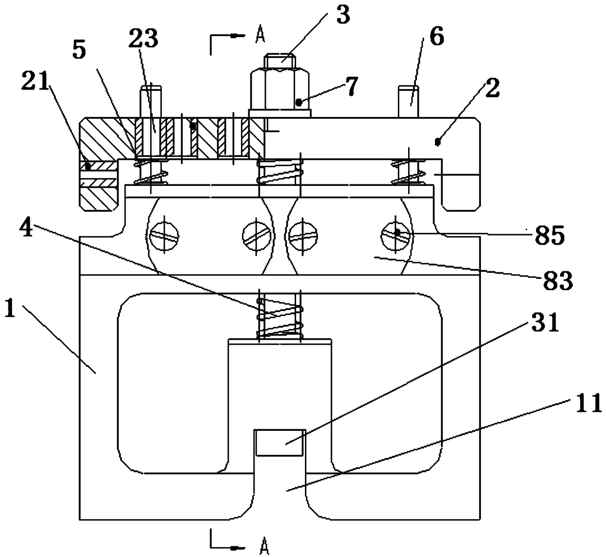
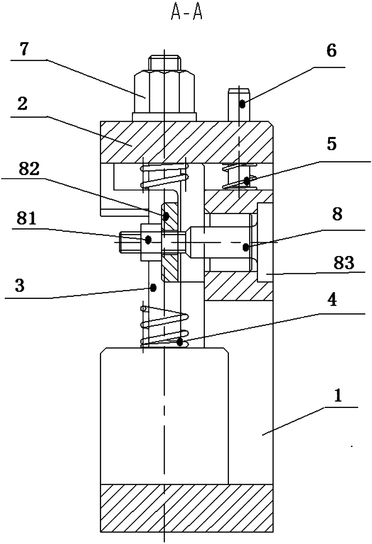
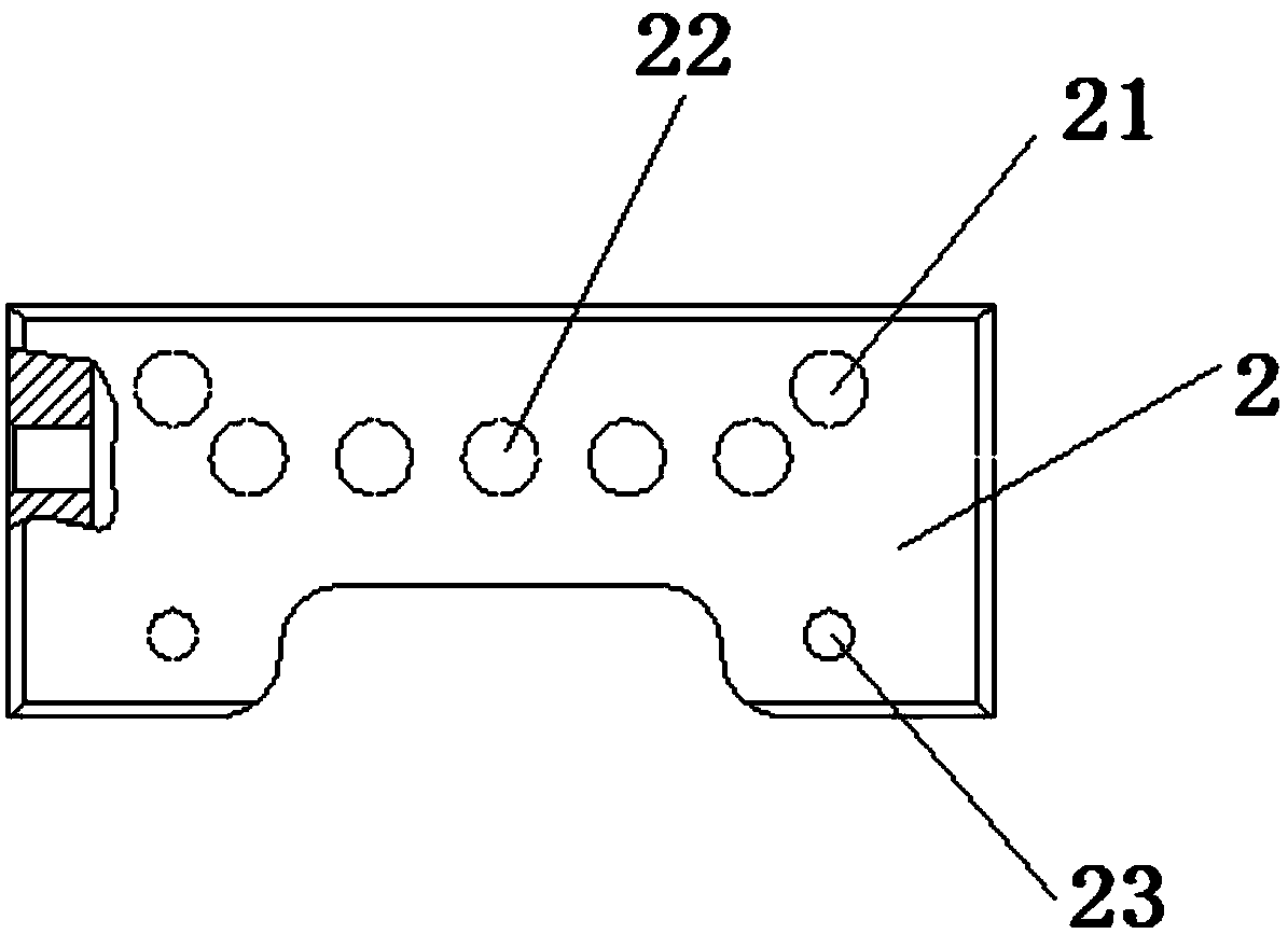
The invention provides a drilling device for workpieces with special-shaped structures. The drilling device comprises a positioning shaft and a drilling template; the positioning shaft and the drilling template designed to match with the workpieces with the special-shaped structures to be machined; a shaft sleeve sleeves the positioning shaft; and an L-shaped right-angled plate connected with theshaft sleeve is contacted with the drilling template in parallel for positioning and clamping from two angles and multiple dimensions of the drilling template surface and the positioning axis. The drilling device is simple, novel and compact in structure and accurate in positioning, and guarantees the size precision of each hole of the workpieces.

Description

technical field [0001] The invention belongs to the field of drilling jigs, in particular to a drilling device for workpieces with special-shaped structures. Background technique [0002] The double-rod DC electric switch machine is used in railway signal products to change the opening direction of the switch, lock the switch switch rail, and respond to the position status of the switch rail. A special-shaped structure workpiece needs to be processed with three M8 threaded holes according to its assembly requirements. and side M4 holes. Its structure is as Figure 8 , Figure 9 and Figure 10 As shown, it includes an L-shaped right-angle plate, and the shaft sleeve is vertically arranged on the L-shaped right-angle plate. Due to its special-shaped structure, it is difficult to guarantee the position of the drilling positioning fixture on the market, and it is not easy to guarantee the size of the direct drilling, and there are easy dimensional deviations between multiple ...

Claims


Application Information

Patent Timeline
IPC IPC(8): B23Q3/06B23B47/28
CPCB23B47/28B23Q3/06
Inventor 王家星魏少敏刘熙皓胡西科
Owner TIANJIN RAILWAY SIGNAL
Why Eureka
Try Eureka