
Passive decoupling mechanism for joint movement of tandem rope-driven manipulator

A joint motion and manipulator technology, applied in the direction of manipulators, program-controlled manipulators, manufacturing tools, etc., can solve the problems of joint motion coupling of serial rope-driven manipulators, and achieve the effects of less wear, less breakage, and simplified design

Pending Publication Date: 2018-12-07
JILIN UNIV
View PDF0 Cites 7 Cited by
  • Summary
  • Abstract
  • Description
  • Claims
  • Application Information

AI Technical Summary

Problems solved by technology

[0004] The technical problem to be solved by the present invention is to overcome the joint kinematic coupling problem of the tandem rope-driven manipulator in the prior art, and provide a tandem rope-driven manipulator Passive decoupling mechanism for joint motion

Method used


Image

  • Passive decoupling mechanism for joint movement of tandem rope-driven manipulator
  • Passive decoupling mechanism for joint movement of tandem rope-driven manipulator
  • Passive decoupling mechanism for joint movement of tandem rope-driven manipulator

Examples


Embodiment Construction

[0036] The present invention is described in detail below in conjunction with accompanying drawing:

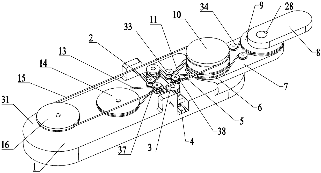
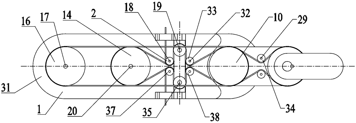
[0037] refer to figure 1 , the passive decoupling mechanism for the joint motion of the serial rope-driven manipulator according to the present invention includes a base system 1, a decoupling module 4, a No. 1 decoupling rope 5, a No. 1 arm system 7, a No. 2 arm 8, and a No. 2 solution Coupling rope 11, No. 2 driving rope 13 and No. 1 driving rope 15;

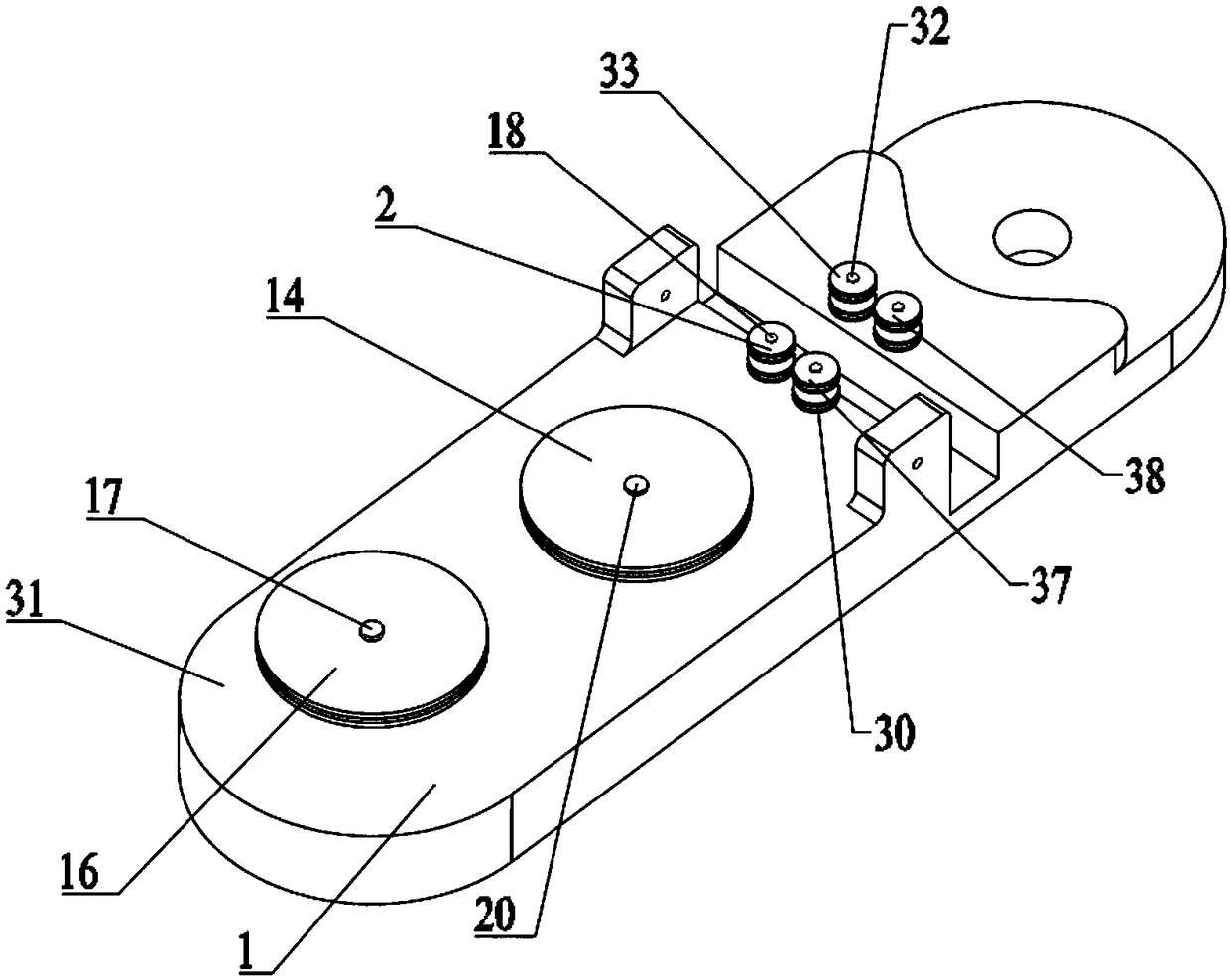
[0038] refer to figure 2 and image 3 , the base system 1 includes No. 1 guide wheel set 2, No. 2 driving wheel 14, No. 1 driving wheel 16, No. 1 pin 17, 2 No. 3 pins 18, No. 2 pin 20, base Plate 31, 2 No. 6 pins 32 with the same structure, No. 2 guide wheel group 33, No. 3 guide wheel group 37 and No. 4 guide wheel group 38.

[0039] Described No. 1 guide wheel set 2 is made up of two small pulleys 30, and two small pulleys 30 are vertically stacked and installed, and their centerlines coincide. The small pulley 30 is d...


PUM


Abstract

The invention discloses a passive decoupling mechanism for joint movement of a tandem rope-driven manipulator, and overcomes the problem of joint movement coupling of the tandem rope-driven manipulator. The passive decoupling mechanism comprises a base system, a decoupling module, a first decoupling rope, a first arm system, a second arm, a second decoupling rope, a second driving rope and a firstdriving rope; the base system comprises a second driving wheel, a first driving wheel and a base plate; the first arm system comprises a first active wheel, a second active wheel, a round shaft and afirst arm plate; the decoupling module is mounted in a rectangular groove of the base plate through a guide rail thereof; the first arm system is mounted in a right polish through hole on the base plate through the lower end of a small-shaft section of the first driving wheel; the second arm is mounted at the right end of the first arm plate by adopting a key and the round shaft; the first driving rope is sleeved in a groove above the first driving wheel and the first active wheel on the base plate; and the first decoupling rope, the second decoupling rope and the second driving rope seriallyconnect the base system, the decoupling module and the first arm system.

Description

technical field [0001] The invention relates to a mechanism for passive decoupling motion, more precisely, the invention relates to a passive decoupling mechanism for the joint motion of a serial rope-driven manipulator. Background technique [0002] Since the first manipulator developed by United Control Corporation in 1958, the serial manipulator has been developed for 60 years. The serial manipulator has gradually developed in two directions: one is miniaturization and the other is large-scale. In the development of large-scale development, the manipulator pursues a higher load capacity; in the process of miniaturization, the manipulator pursues a slimmer body shape in order to work in a narrow working space. Many researchers have proposed methods to reduce the size of the manipulator by using mechanisms such as ropes, gears, and connecting rods as power transmission media. Using the rope as the power transmission medium can greatly simplify and reduce the kinematic join...

Claims


Application Information

Patent Timeline
IPC IPC(8): B25J9/00B25J9/10
CPCB25J9/0009B25J9/104
Inventor 于立娟魏宁波李栋吴国民
Owner JILIN UNIV
Learn More