Road-bridge site installation structure, method and crane

An on-site installation and crane technology, which is applied to bridges, cranes, bridge parts, etc., can solve the problems of hindering the opening of original roads, increasing construction costs, occupying ground space, etc., and achieves the effects of saving ground space, reducing weight and improving work efficiency

Active Publication Date: 2018-12-07
张跃
View PDF11 Cites 2 Cited by
  • Summary
  • Abstract
  • Description
  • Claims
  • Application Information

AI Technical Summary

Problems solved by technology

[0003] The use of this kind of tower crane for hoisting mainly has the following defects: (1) The tower cranes are all located on the ground, and at least two tower cranes are required to complete the operation, which takes up a lot of ground space; (2) During the tower crane operation, the construction area needs to be fenced Enclosed to prevent passing pedestrians or vehicles from entering the construction area by mistake, but this will occupy the original lane, thereby hindering the opening of the original road; (3) The existing bridges are basically formed by splicing cast-in-place components, or using Prefabricated components and cast-in-place components are combined and spliced, so that the tower crane works with the scaffolding, and the construction of the scaffolding is not only time-consuming and laborious, but also occupies the ground space, and the cost is greatly increased; (4) The existing bridge construction needs to set up temporary construction on the ground The channel is convenient for placing or transporting building materials, which not only occupies the ground space, but also increases the construction cost; (5) The existing tower crane has a complex structure and heavy weight, which not only occupies the ground space, but also greatly increases the cost of materials; (6) The existing tower crane Requires height adjustment, greatly improving duty cycle

Method used


Image

  • Road-bridge site installation structure, method and crane

Examples


Embodiment Construction

[0036] The present invention will be further described in detail below in conjunction with the accompanying drawings and specific embodiments.

[0037] A road and bridge site installation method, comprising the following steps:

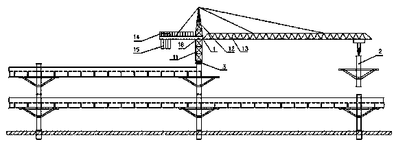
[0038] S1: Install the first crane 1 and the second crane respectively on the top of the two piers.

[0039] Specifically, when the bridge is usually installed from the starting point, it mainly includes the following two options:

[0040] The first option involves the following steps:

[0041] S101: First install two bridge piers 2, and the first bridge pier is hoisted to the target position by other tower cranes and fixed;

[0042] S102: The tower crane hoists the first crane to the top of the first pier for fixing;

[0043] S103: installing the second pier to the target position by the first crane;

[0044] S104: Using the first crane to hoist the second crane to the top of the second pier and fix it.

[0045] S105: Use the first crane and / or ...


PUM


Abstract

A road and bridge field installation structure, method and crane are disclosed, the installation structure comprises: a crane is installed at the top of a pier, and a bridge member is hoisted by the crane. The invention also includes a road and bridge field installation method and a crane. On the one hand, the invention has the advantages of high working efficiency, low cost, no occupying ground space, no occupying original lane, no construction temporary passage and the like; On the other hand, the crane of the invention does not need to be provided with a tower body and a hydraulic prop foradjusting the height, thereby greatly reducing the weight, reducing the cost and improving the safety factor.

Description

technical field [0001] The invention relates to the field of bridge installation, in particular to a road and bridge field installation structure, method and crane. Background technique [0002] In the existing on-site installation of bridge components, the pier and bridge body components are mainly lifted by tower cranes. The tower body of the tower crane is composed of multi-section brackets. The height of the tower body can be adjusted through hydraulic props. Lift a bracket after the space, hang it on the boom and push the bracket in to make the tower rise. Lifting up and down in this way realizes lifting operations in different positions. [0003] The use of this kind of tower crane for hoisting mainly has the following defects: (1) The tower cranes are all located on the ground, and at least two tower cranes are required to complete the operation, which takes up a lot of ground space; (2) During the tower crane operation, the construction area needs to be fenced Encl...

Claims


Application Information

Patent Timeline
IPC IPC(8): E01D21/00E01D19/02B66C23/16B66C23/62B66C23/84B66C13/08
CPCB66C13/08B66C23/166B66C23/62B66C23/84E01D19/02E01D21/00
Inventor 张跃
Owner 张跃
Why Eureka
Try Eureka