Reinforcing device and method for bending main material of tower leg of power transmission angle steel tower

A technology for reinforcing devices and transmission towers, applied in the directions of towers, building maintenance, building types, etc., can solve the problem that the reinforced angle steel cannot be closely attached to the bending part, so as to ensure the safety of use, ensure the firmness and safety of use, and increase the cross-section. Effect of Moment of Inertia

Active Publication Date: 2018-12-07
ELECTRIC POWER RESEARCH INSTITUTE OF STATE GRID SHANDONG ELECTRIC POWER COMPANY +2
View PDF9 Cites 3 Cited by
  • Summary
  • Abstract
  • Description
  • Claims
  • Application Information

AI Technical Summary

Problems solved by technology

[0004] The present invention aims at the above-mentioned deficiencies in the prior art, and provides a reinforcement device for the bending of the main material of the transmission angle steel tower leg. By adding a filling plate at the bending position, the filling plate has a pulling force on the bending position, and the bending position is strengthened by the filling plate. It realizes the connection between the curved part and the reinforced angle steel, and solves the problem that the original reinforced angle steel and the curved part cannot be closely attached. The rectangular rotary structure composed of the reinforced angle steel and the main material of the transmission tower increases the section moment of inertia. Improve the bending resistance of the bending part and realize the reinforcement of the bending part

Method used


Image

  • Reinforcing device and method for bending main material of tower leg of power transmission angle steel tower
  • Reinforcing device and method for bending main material of tower leg of power transmission angle steel tower
  • Reinforcing device and method for bending main material of tower leg of power transmission angle steel tower

Examples


Embodiment Construction

[0031] The following will clearly and completely describe the technical solutions in the embodiments of the present invention with reference to the accompanying drawings in the embodiments of the present invention. Obviously, the described embodiments are only some, not all, embodiments of the present invention. Based on the embodiments of the present invention, all other embodiments obtained by persons of ordinary skill in the art without making creative efforts belong to the protection scope of the present invention.

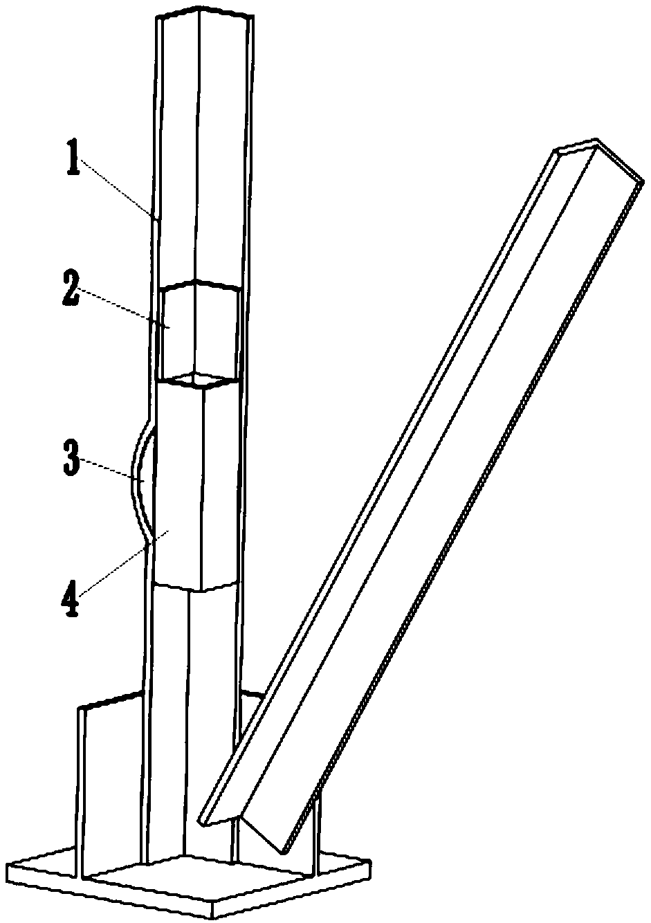
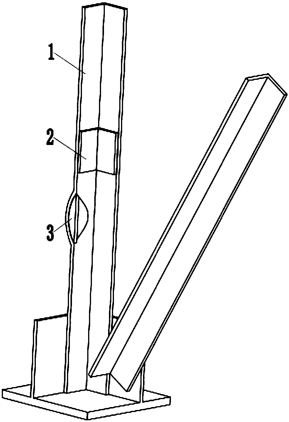
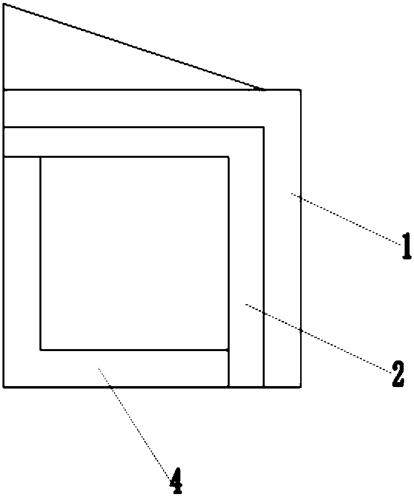
[0032] Such as figure 1 As shown, a reinforcement device for bending the main material of the tower leg of the transmission angle steel tower includes a main material 1 of the transmission tower and a reinforced angle steel 4. The main material 1 of the transmission tower is provided with a bending part 101. Main material 1 connection, also includes transition angle steel 2, filler plate 3, such as figure 2 As shown, the filling plate 3 is arranged on the in...


PUM


Abstract

The invention discloses a reinforcing device and method for bending a main material of a tower leg of a power transmission angle steel tower. The device comprises the power transmission tower main material and reinforcing angle steel, and the power transmission tower main material is provided with a bent part. The device also comprises transition angle steel and a filling plate, the filling plateis arranged on the inner side of the bent part, the outer side of the filling plate is aligned with the end of the power transmission tower main material, one side of the filling plate is attached tothe inner wall of the bent part and is fixedly welded, and the other side of the filling plate is a straight edge and is aligned with the inner wall of the power transmission tower main material; thereinforcing angle steel is arranged on the inner side of the power transmission tower main material, the reinforcing steel angle and the power transmission tower main material form a rectangular rotating structure, and the reinforcing angle steel is in butt joint with the straight edge of the filling plate; the reinforcing angle steel is fixedly welded to the inner wall of the power transmission tower main material and the filling plate, the transition angle steel is attached to the inner wall of the power transmission tower main material, the two sides of the transition angle steel are fixedly welded to the power transmission tower main material, and the lower end of the transition angle steel is fixedly welded to the reinforcing angle steel.

Description

technical field [0001] The invention relates to the technical field of transmission tower reinforcement, in particular to a reinforcement device and a reinforcement method for bending the main material of a transmission angle steel tower leg. Background technique [0002] As an important supporting equipment for transmission lines, transmission towers are the infrastructure to ensure line stability and grid security. The main components of the transmission angle steel tower are angle steel structures, which form a space truss structure through bolt connections. In actual operation, due to external force damage, such as vehicle impact, fire and other reasons, the strength of the angle steel parts of the transmission tower will be bent and deformed. For angle steel parts such as inclined materials and auxiliary materials, parts can be replaced. However, for main materials, replacement of parts in the on-site environment will cause the tower to become unstable and overturned, ...

Claims


Application Information

Patent Timeline
Patent Type & Authority Applications(China)
IPC IPC(8): E04H12/08E04G23/02
CPCE04G23/0218E04H12/08Y02E10/72
Inventor 杜宝帅菅明健张忠文李新梅邓化凌李文索帅
Owner ELECTRIC POWER RESEARCH INSTITUTE OF STATE GRID SHANDONG ELECTRIC POWER COMPANY
Why Eureka
Try Eureka