Machining technology for engine drive sleeves

An engine-driven and processing technology, applied in the field of metal machining, can solve the problems of reducing the overall performance of parts, low material utilization, and easy damage to broaches, and achieve the effects of simplifying the manufacturing process, high production efficiency, and reducing manufacturing costs.

Inactive Publication Date: 2016-07-06
JIANGSU HAIYU MACHINERY
View PDF6 Cites 9 Cited by
  • Summary
  • Abstract
  • Description
  • Claims
  • Application Information

AI Technical Summary

Problems solved by technology

The disadvantages of using this existing process mainly include: due to the traditional broaching process, pre-drilling, inner circle and other processes are required, so the process is complicated and the processing cost is high; mechanical cutting belongs to the material removal forming method , the material utilization rate is low, resulting in a large amount of material waste
In addition, in the existing process, the drilling and turning of the forging blank will cut a large number of forging streamlines, thereby reducing the overall performance of the part; the broach in the broaching process needs to be specially customized, especially in the production of small diameter When splined, the broach is particularly easy to damage, and the manufacturing cost is relatively high

Method used


Image

  • Machining technology for engine drive sleeves
  • Machining technology for engine drive sleeves
  • Machining technology for engine drive sleeves

Examples


Embodiment Construction

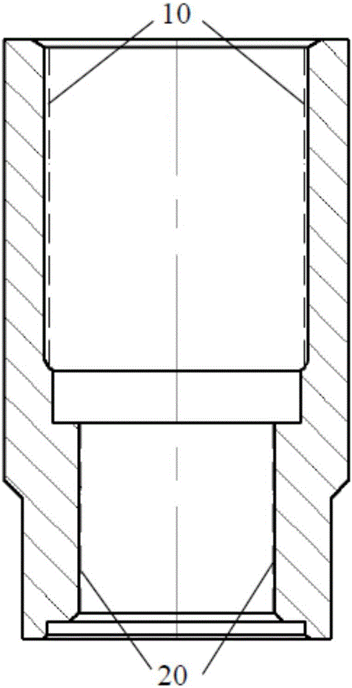
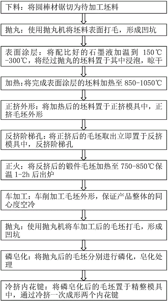
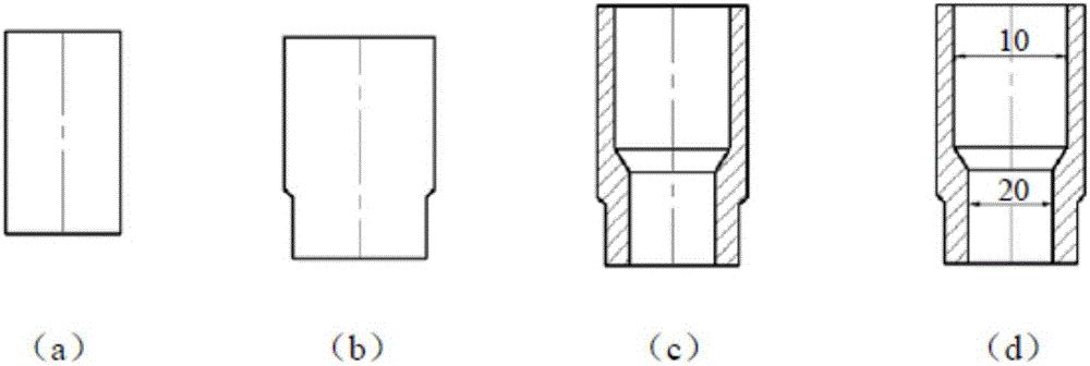
[0025] combine figure 2 The forging process of a new engine drive sleeve of the present invention is described in detail as follows.

[0026] Such as figure 2 The forging process flow chart of the shown engine drive sleeve of the present invention and image 3 The schematic diagram of the forming process of the drive sleeve shown in the present invention, the processing technology of a kind of improved engine drive sleeve of the present invention comprises the following steps: blanking, that is, sawing the round bar steel material into a blank to be processed (see image 3 In (a)); shot blasting, that is, mixing round steel shot and water chestnut sand steel shot in an appropriate proportion, using a shot blasting machine to roughen the surface of the billet to form pits; surface coating, that is, to mix a good graphite liquid Heating to 150°C-300°C, soaking the shot blasted billet in it for 1-3 minutes, and drying; heating, the billet that is about to complete the surface...


PUM


Abstract

The invention provides an improved machining technology for engine drive sleeves. The machining technology comprises the steps of blanking, shot blasting, surface coating forming, heating, forward extruding of appearances, reverse extruding of step holes, normalizing, turning, shot blasting, phosphorus saponifying and cold extruding of internal splines for forming two internal splines at a time. The machining technology avoids subsequent cutting processes such as hole drilling and gear broaching and belongs to chip-less machining methods; by adopting the solid forging technology, a lot of metal flow lines are prevented from being cut, and the whole mechanical property is better; two internal splines can be formed simultaneously through the cold extruding technology, and therefore the raw material and the machining time can be saved to a great extent, the manufacturing technology can be simplified, the manufacturing cost can be lowered, and the surfaces of the internal splines are reinforced in the cold forming process of the internal splines. The machining technology has the advantages that the production efficiency is high, the manufacturing cycle of products is short, and the whole competitiveness of the products is improved.

Description

technical field [0001] The invention relates to the technical field of metal machining, in particular to a forging process of an engine drive sleeve. Background technique [0002] The engine drive sleeve is a key component used in the engine transmission system, from figure 1 As can be seen from the part structure diagram of the shown drive sleeve, the part has two internal splines 10 and 20, one large and one small. The internal spline is a torque transmission part in automobile movement, its manufacturing process level and product quality directly affect the quality of the torque transmission assembly; at the same time, the engine drive sleeve is often subjected to impact loads and high working speeds during work, which requires the engine The drive sleeve has high strength and hardness and good toughness at the same time, that is, it has an excellent combination of strength and toughness. Because forging can eliminate defects such as loose cast state produced during met...

Claims


Application Information

Patent Timeline
Patent Type & Authority Applications(China)
IPC IPC(8): B23P15/00
CPCB23P15/00
Inventor 顾成义沈华宾樊博闻饶广谢国兵梅荣银
Owner JIANGSU HAIYU MACHINERY
Why Eureka
Try Eureka